9D-1 Exterior Parts:
Exterior Parts
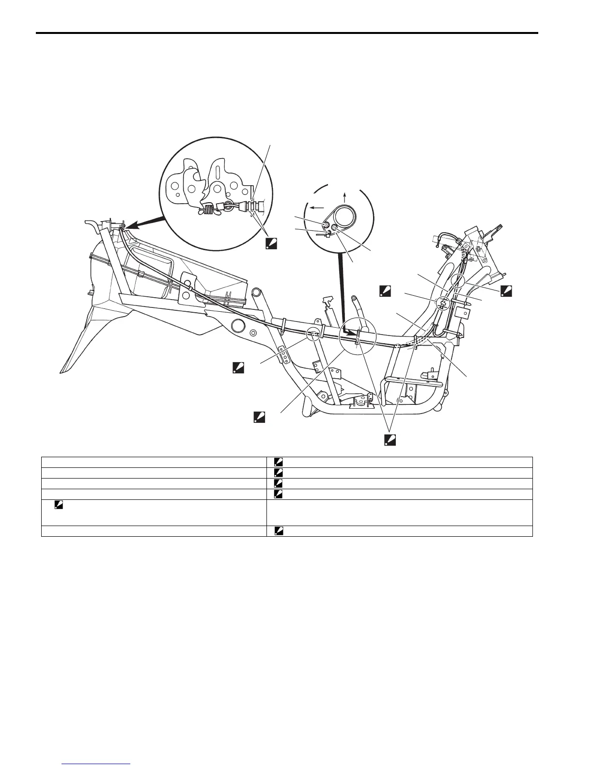
Schematic and Routing Diagram
Seat Lock Cable Routing Diagram
B705H19402001
1
2
3
4
5
“A”
“C”
“B”
“D”
5
4
INNER
UPPER
3
6
“E”
“F”
I705H1940050-04
1. Seat lock cable No. 1 “A”: Pass the seat lock cable No. 2 through front of the seat lock cable No. 1.
2. Seat lock cable No. 2 “B”: Pass the seat lock cable No. 1 through inside of the frame.
3. Brake-lock cable “C”: Pass the cables through inner side of the frame.
4. Starter motor lead wire “D”: Pass the cables through bottom and inner side of the frame.
5. Clamp
: Clamp the brake-lock cable, starter motor lead wire and seat
lock cable.
“E”: Seat lock cable set position
6. Seat lock cable “F”: Change set position only when seat locking or releasing is impossible.

 Loading...


