1D-14 Engine Mechanical:
6) Remove the TP sensor (8) and STV sensor (9).
NOTE
Prior to disassembly, mark each sensors
original position with a paint or scribe “A” for
accurate reinstallation.
CAUTION
!
Never remove the STVA (10) from the throttle
body.
CAUTION
!
Never remove the throttle valve (11) and
secondary throttle valve (12).
Assembly
Assembly is the throttle body in the reverse order of
removal. Pay attention to the following points:
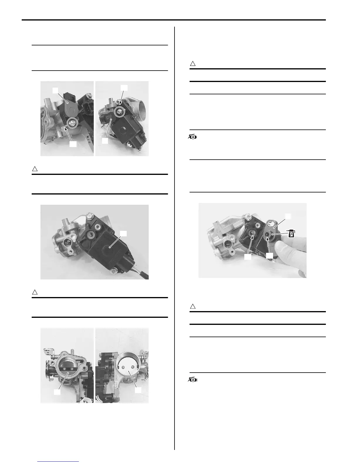
• With the STV fully opened, install the STP sensor (1).
CAUTION
!
Apply thin coat of the engine oil to the O-ring.
NOTE
• Align the secondary throttle shaft end “A”
with the groove “B” of STP sensor.
• Apply grease to the secondary throttle
shaft end “A”.
: Grease 99000–25010 (SUZUKI SUPER
GREASE A or equivalent)
NOTE
Make sure the STP valve open or close
smoothly. If the STP sensor adjustment is
necessary, refer to “STP Sensor Adjustment
in Section 1C (Page1C-5)”.
• With the throttle valve fully closed, install the TP
sensor (2).
CAUTION
!
Apply thin coat of the engine oil to the O-ring.
NOTE
• Align the throttle shaft end “C” with the
groove “D” of TP sensor.
• Apply grease to the secondary throttle
shaft end “C”.
: Grease 99000–25010 (SUZUKI SUPER
GREASE A or equivalent)
“A”
8
“A”
9
I705H1140212-02
10
I705H1140213-01
11
12
I705H1140216-01
“A”
“B”
1
I705H1140214-02

 Loading...


