EasyManua.ls Logo

Suzuki GSF650A - ABS Unit Diagram

Suzuki GSF650A
697 pages
Print Icon
To Next Page IconTo Next Page
To Previous Page IconTo Previous Page
Loading...
ABS: 4E-8
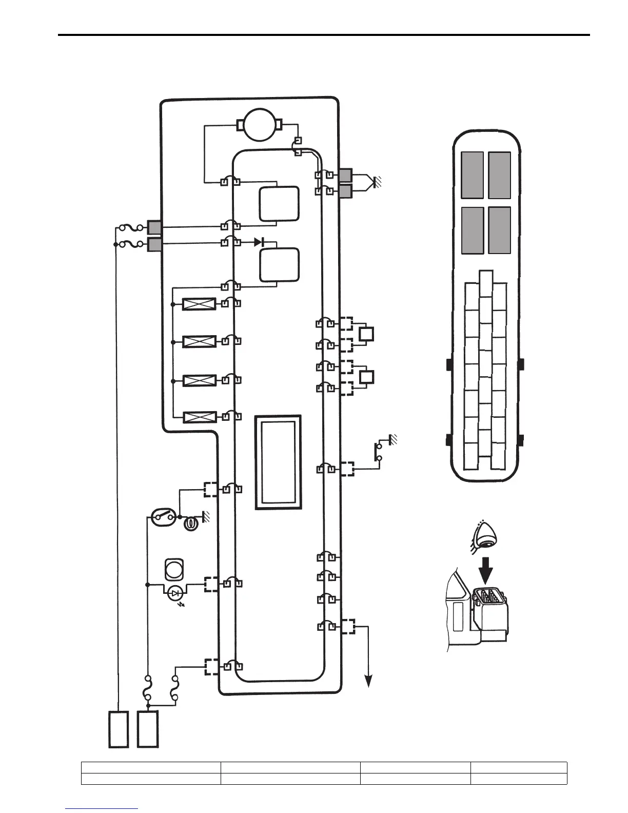
ABS Unit Diagram
B817H24502002
Refer to “Wire Color Symbols in Section 0A (Page 0A-5)”.
Battery
Ignition
Ignition
ABS
Brake light
switch
Brake light switch
ABS
indicator light
Solenoid
Battery (+)
Fail
safe
relay
Motor
relay
Ground
Front
wheel
speed
sensor
Rear
wheel
speed
sensor
Mode
select
coupler
ABS control unit
M
Ground
24
25
2
2
3
3
12
12
12
13
13
13
18
18
18
10
10
10
4
4
11
11
21
16
16
16
8
9
2
3
4
10
21
12
13
16
18
24
8
9
25
Motor
ground
SDS
O/Y Br W/B
R/Bl R/B
B/W B/W
W/YB/YB/R
OGr
W/R
ABS motor fuse (20 A)
ABS valve fuse (15 A)
“A”
“B” “C”
“D”
“E”
“F”
“G”
I718H1450021-04
“A”: Rear brake solenoid OUT “C”: Front brake solenoid OUT “E”: Fail safe (+) B “G”: Motor (+) B
“B”: Rear brake solenoid IN “D”: Front brake solenoid IN “F”: Motor relay (+) B

Table of Contents