ABS: 4E-60
DTC “46” (C1646): Wheel Speed Sensor Circuit Short (R)
B817H24504020
Wiring Diagram
Refer to “ABS Unit Diagram (Page 4E-8)”.
Troubleshooting
Possible Cause
• Poor contact in the rear wheel speed sensor coupler
• Faulty rear wheel speed sensor, etc.
Step Action Yes No
1 1) Turn the ignition switch OFF.
2) Remove the left frame cover. Refer to “Exterior Parts
Removal and Installation (GSF650/S/A/SAK7) in Section
9D (Page 9D-6)”.
3) Remove the fuse box mounting bolt. Refer to “ABS
Control Unit Coupler Disconnect and Connect (Page 4E-
69)”.
4) Check the ABS control unit coupler for loose or poor
contacts. If OK, then disconnect the ABS control unit
coupler.
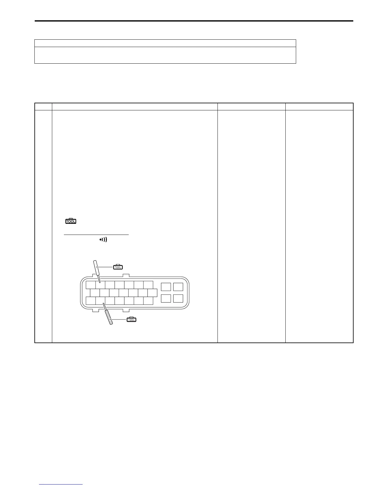
5) Check for continuity between “2” (B/Y) and “18” (W/Y) at
the coupler.
Special tool
(A): 09900–25008 (Multi-circuit tester set)
Tester knob indication
Continuity ( )
ABS control unit coupler (Harness end)
Is there continuity between “2” and “18”?
• Inspect the wire
harness. (Faulty
sensor wire)
• Faulty rear wheel
speed sensor
Go to Step 2.
24 25
18
10
12 13
16
2
3
4
21
89
(A)
(A)
I718H1450093-02

 Loading...


