46
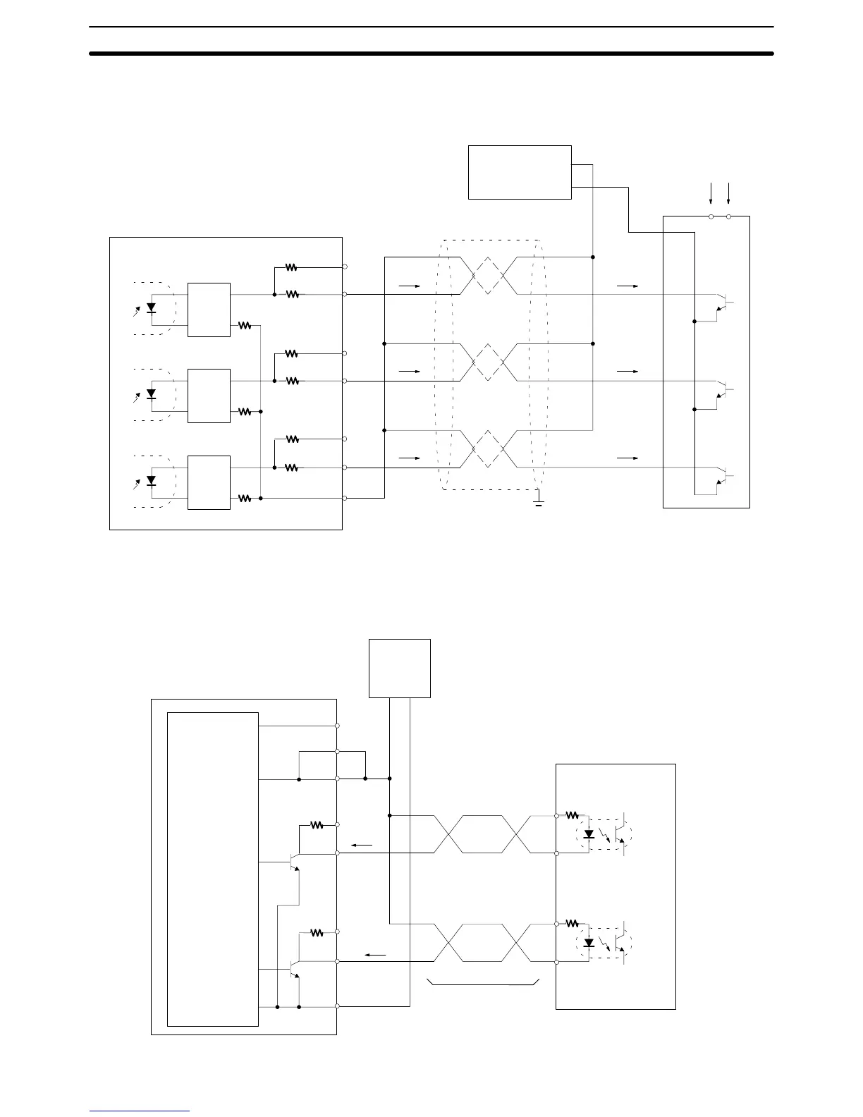
For example, the following diagram shows the connection of an encoder with
phases A, B, and C.
CQM1-CPU43-EV1
(Do not share the power supply with other I/O.)
Encoder
Power provided here
12-VDC
power
supply
Twisted-pair wire with shield
Encoder
output
Rectifier
Rectifier
Rectifier
24 V
12 V
COM
3
10
4
11
2
9
1
24 V
12 V
24 V
12 V
12 VDC
0 V
E
I
A
I
R
I
Z
I
A
I
R
I
Z
(+)
(–)
2) Pulse Output Connection
In these two example diagrams, the CQM1-CPU43-EV1 is connected to a 5-V
input motor driver.
• When a 5-VDC Power Supply is Used
CQM1-CPU43-EV1
(Do not share the power supply with other I/O.)
Motor driver (for 5-V input)
Example: R = 220Ω
CCW
input
CW
input
Twisted-pair wire
5-VDC
power
supply
Approx.
15 mA
1.6 kΩ
1.6 kΩ
24-VDC power
supply input
5-VDC power
supply input
CCW pulse
output
CW pulse
output
15
7
8
13
5
14
6
12
+–
Approx.
15 mA
(+)
(–)
(+)
(–)
Unit Specifications
Section 2-6