45
Wiring Examples 1) Pulse Input Connection
Depending on the count mode, the outputs from the encoder are connected to
Port 1 and Port 2 as shown below.
Ports 1 and 2 Encoder outputs
Pin
no.
Signal name Phase-difference
input mode
Pulse + direction
input mode
Inc/Dec pulse
input mode
3, 10 Encoder input A Encoder phase
A output
Direction signal
output
Decrement pulse
output
4, 11 Encoder input B Encoder phase
B output
Pulse output Increment pulse
output
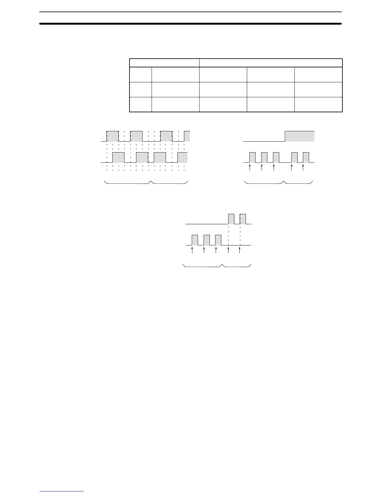
Phase-difference Input Mode
Pulse and Direction Input Mode
Encoder input A
Encoder input B
Increment Decrement
Inc/Dec Pulse Input Mode
12345678765432 123 21
Encoder input A
Encoder input B
Increment Decrement
12321
Encoder input A
Encoder input B
Increment Decrement
Unit Specifications
Section 2-6