44
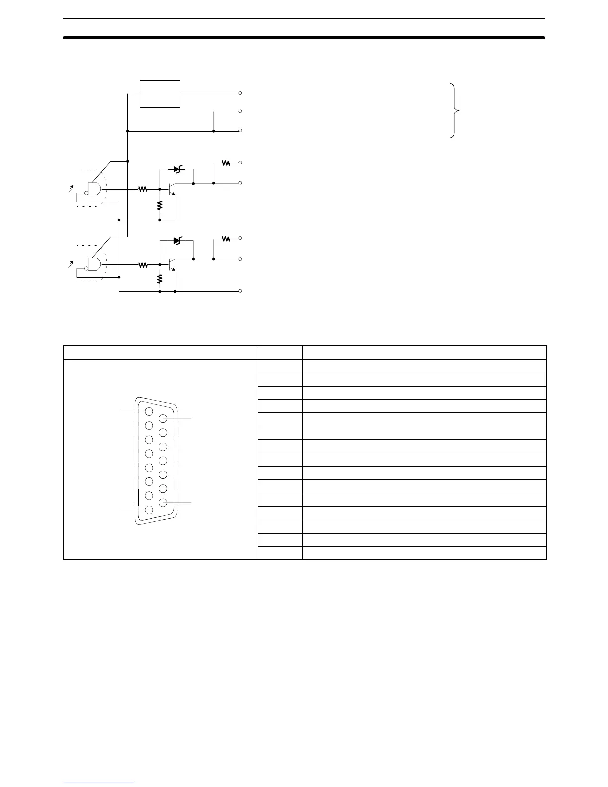
• Pulse Output Section
Name
Provide either one
of these power
supplies. Do not
provide both, or
the circuits will be
damaged.
Low voltage
circuit
1.6 kΩ (1/2 W)
1.6 kΩ (1/2 W)
Pin no.
15 Power supply input for output 24 VDC. . . .
7 Power supply input for output 5 VDC. . . . .
8 Power supply input for output 5 VDC. . . . .
13 CCW pulse output (with 1.6-kΩ resistance). . . .
5 CCW pulse output. . . . .
14 CW pulse output / PWM output (with 1.6-kΩ resistance). . . .
6 CW pulse output / PWM output. . . . .
12 Output common (0 V). . . .
Note Ports 1 and 2 are the same.
Connector Pin Arrangement
Pin arrangement Pin no. Signals
1 Input common
2 Pulse input Z: 24 VDC
3 Encoder input A: 24 VDC
4 Encoder input B: 24 VDC
8
15
5 CCW pulse output
6 CW pulse output / PWM output
7 Power supply input for output: 5 VDC
8 Power supply input for output: 5 VDC
9 Pulse input Z: 12 VDC
10 Encoder input A: 12 VDC
12 Output common (0 V)
13 CCW pulse output (with 1.6-Ω resistance)
14 CW pulse output / PWM output (with 1.6-Ω resistance)
15 Power supply input for output: 24 VDC
Unit Specifications
Section 2-6