Removal and Installation Procedures
SPG600 & SPG300 Sync Pulse Generators Service Manual 6-7
Equipment Required. Most modules in the sync pulse generator can be removed
with a screwdriver handle mounted with a #2 Phillips tip. Use this tool whenever a
screwdriver is specified in that step. All equipment required to remove and reinstall
each module is listed in the first step of its procedure.
Instrument Orientation
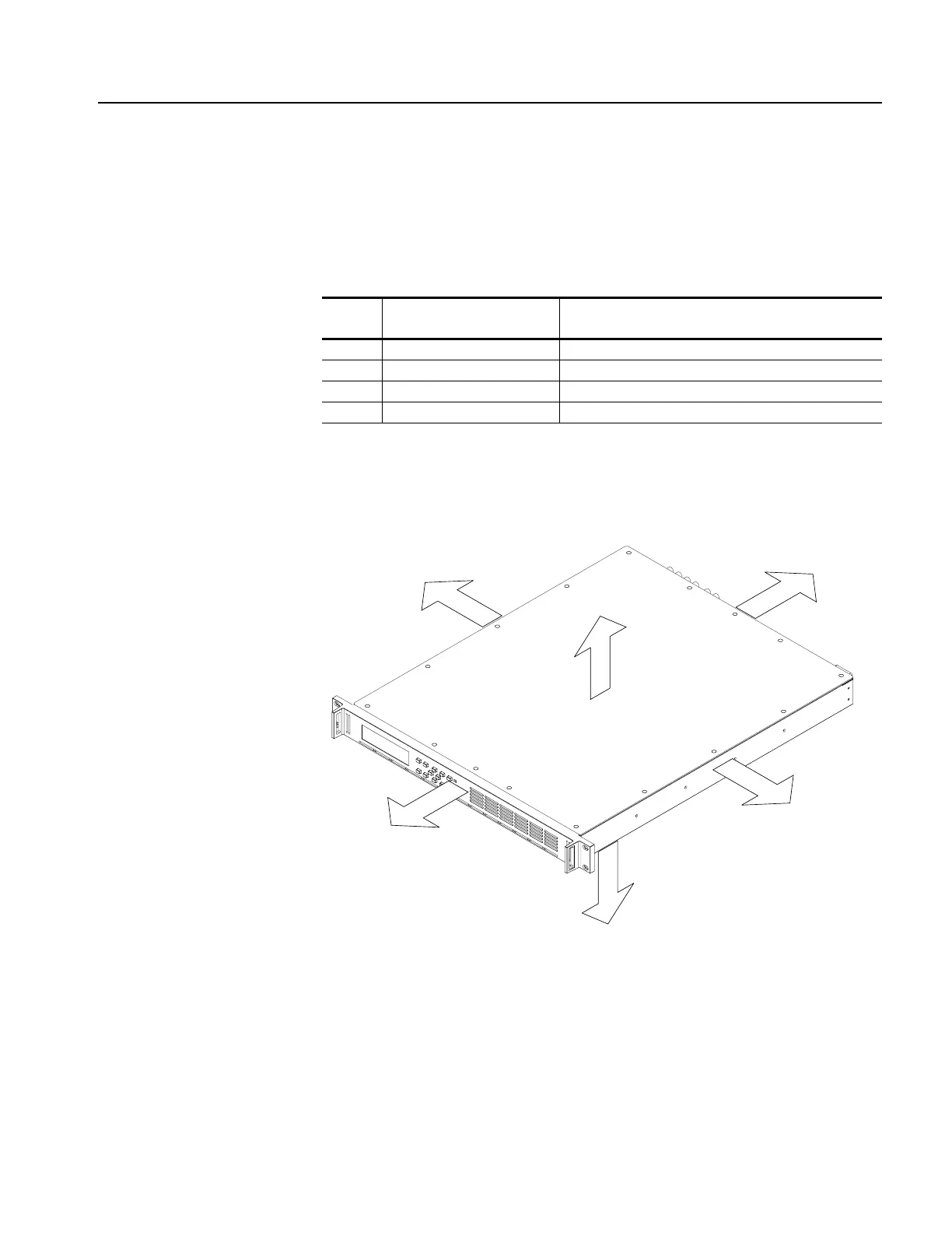
In this manual, procedures refer to “front,” “back,” “top,” etc. of the sync pulse
generator. Figure 6-1 shows how the sides are referenced.
Figure 6-1: Instrument orientation (SPG600)
Table 6-2: Tools required for module removal
Item
No. Name Description
1 Screwdriver handle Accepts Phillips-driver bits
2 #1 Phillips tip Phillips-driver bit for #1 size screw heads
3 #2 Phillips tip Phillips-driver bit for #2 size screw heads
4 5 mm Nut Driver Socket or driver for 5 mm nuts
TOP
BACK
LEFT
RIGHT
BOTTOM
FRONT
 Loading...


