Performance Verification
4-12 SPG600 & SPG300 Sync Pulse Generators Service Manual
44. Move the BNC cable connection from CH 6 connector to the CH 7 connector
on the sync pulse generator.
45. Repeat steps 32 and 33.
46. Move the BNC cable connection from CH 7 connector to the CH 8 connector
on the sync pulse generator.
47. Repeat steps 32 and 33.
Serial Digital Output
This test verifies that serial digital signals are output correctly from the SDI 1 and
SDI 2 connectors. The following equipment is required for the test:
Video measurement set
75 Ω BNC cable
75 Ω coaxial terminator
Perform the following procedure to verify that serial digital signals are output
correctly from the SDI 1 and SDI 2 connectors.
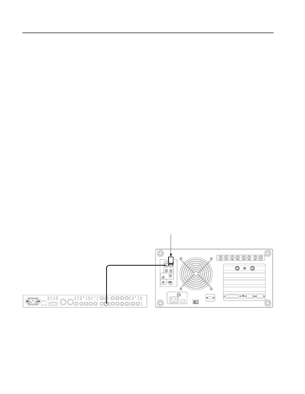
1. Use the 75
Ω BNC cable to connect SDI 1 connector on the sync pulse
generator to the SDI Ch.A connector on the video measurement set rear panel.
See Figure 4-4.
2. Use the 75
Ω coaxial terminator to terminate the other loop through to the SDI
Ch.A connector on the video measurement set rear panel. See Figure 4-4.
Figure 4-4: Equipment connection for verifying the serial digital outputs
SPG600 rear panel
75
Ω coaxial terminator
Video measurement set
rear panel (VM700T Option 01/11/1S/40)
75 Ω BNC cable
 Loading...


