Performance Verification
SPG600 & SPG300 Sync Pulse Generators Service Manual 4-17
3. Recall Factory Default preset as follows:
a. Press the SYSTEM button to display the System menu.
b. Press the ENTER button to display the Preset submenu.
c. Press the left (
W) or right (X) arrow button to select Factory Default.
d. Press the ENTER button to recall the factory default settings.
4. Use the oscilloscope to measure that the signal amplitude is within the range
of 900 mV to 1100 mV.
5. Change the BNC cable connection from the AES 1+2 connector to the AES
3+4 connector on the sync pulse generator.
6. Repeat step 4.
7. Change the BNC cable connection from the AES 3+4 connector to the AES
5+6 connector on the sync pulse generator.
8. Repeat step 4.
9. Change the BNC cable connection from the AES 5+6 connector to the AES
7+8 connector on the sync pulse generator.
10. Repeat step 4.
11. Disconnect the BNC cable and the 75
Ω terminator from the oscilloscope CH1
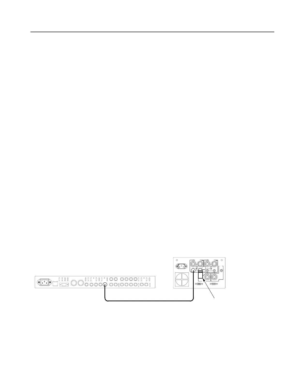
input connector, and then connect the BNC cable to the CH1-2 BNC connector
on the digital audio monitor rear panel. See Figure 4-6.
12. Use the 75
Ω coaxial terminator to terminate the other loop through to the
CH1-2 BNC connector on the digital audio monitor rear-panel.
Figure 4-6: Second equipment connection for verifying the serial digital audio outputs
SPG600 rear panel
75
Ω BNC cable
Digital audio monitor
rear panel (764)
75 Ω coaxial terminator
 Loading...


