Adjustment Procedure
5-2 SPG600 & SPG300 Sync Pulse Generators Service Manual
Master Clock Frequency Adjustment
Procedure
Perform the following procedure to adjust the master clock frequency.
Initial Setups.
Signal Generator:
Frequency . . . . . . . . . . . . . . . . . 10.000000 MHz
Output level. . . . . . . . . . . . . . . . 8 dBm
Procedure.
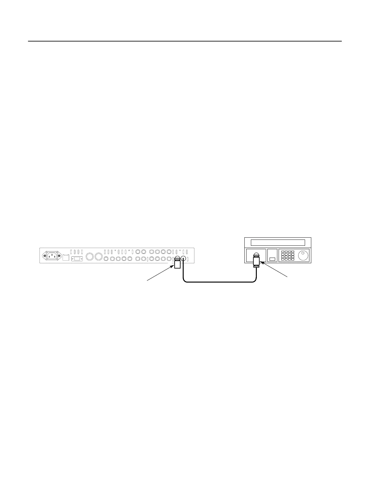
1. Use the 75
Ω BNC cable and the 50 Ω -to-75 Ω minimum loss attenuator to
connect the REF connector on the sync pulse generator to the output connector
on the signal generator as shown in Figure 5-1.
2. Use the 75
Ω coax terminator to terminate the other REF connector on the sync
pulse generator as shown in Figure 5-1.
Figure 5-1: Equipment connection for adjusting master clock frequency
3. Press the VIDEO, GENLOCK, and PANEL ENABLE buttons
simultaneously, and then release the VIDEO and GENLOCK buttons to
restart the instrument in Factory mode.
4. Set the genlock source of the sync pulse generator as follows:
a. Press the GENLOCK button to display the Genlock menu.
b. Press the up (
S) or down (T) arrow button to select GENLOCK
SOURCE.
c. Press the left (
W) or right (X) arrow button to select CW 10 MHz.
d. Press the ENTER button.
5. Press the SYSTEM button to display the System menu.
SPG600 rear panel
Signal generator
75 Ω BNC cable
50
Ω-to-75 Ω minimum
loss attenuator
75 Ω coax terminator
 Loading...


