Removal and Installation Procedures
6-18 SPG600 & SPG300 Sync Pulse Generators Service Manual
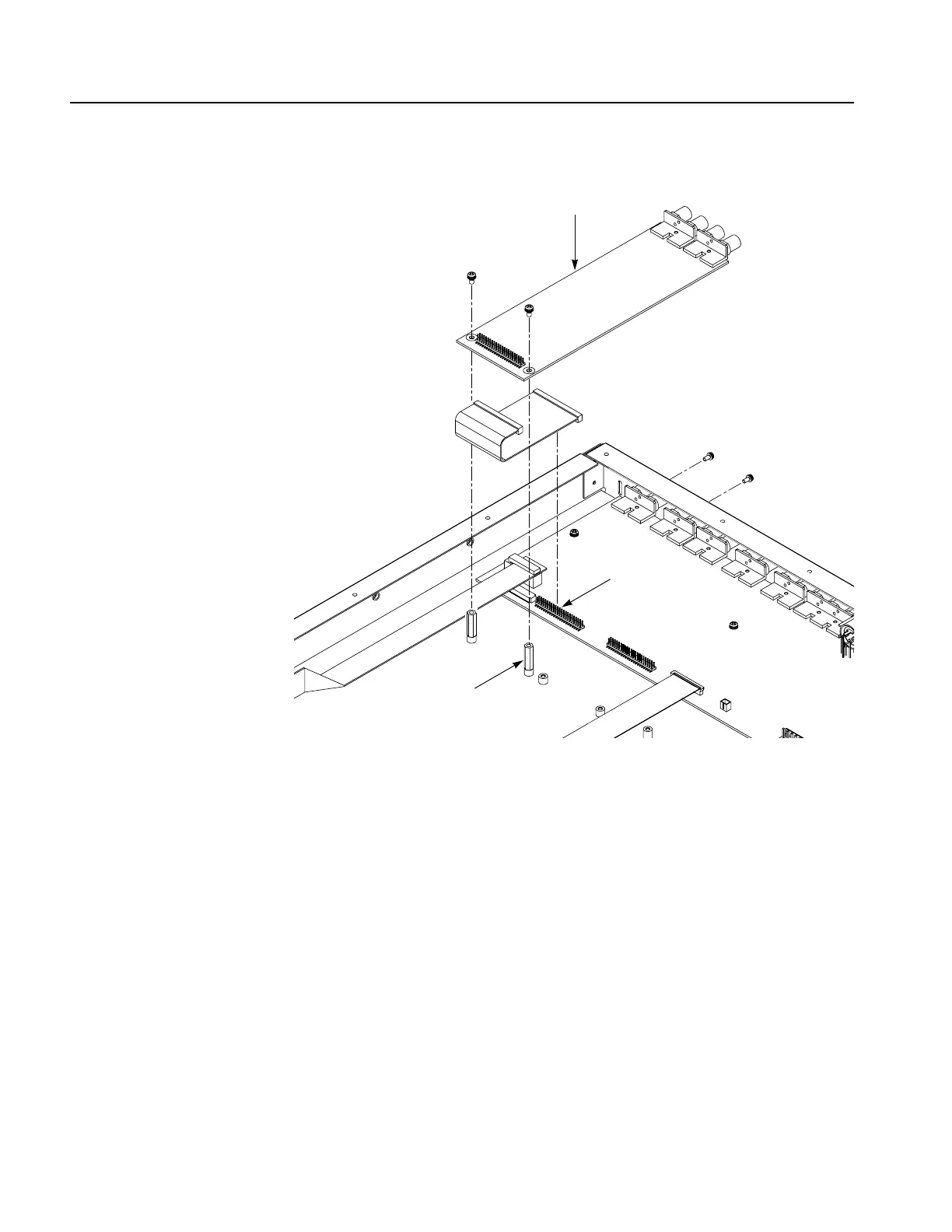
Figure 6-9: A30 Analog board removal
A40 SDI Board (Option 03
Only)
1. Locate module to be removed: Locate the A40 SDI board in the locator
diagram SPG600 Internal modules, Figure 6-3, on page 6-9.
2. Orient the instrument: Set the SPG600 so its bottom is down on the work
surface and its right side is facing you.
3. Remove the A40 SDI board: See Figure 6-10.
a. Unplug the cable from the A10 Main board at J1.
b. Use a screwdriver with #1 Phillips tip to remove the two screws securing
the A40 SDI board to the rear of the chassis.
Spacer post
A30 Analog board
J600
A10 Main board
 Loading...


