Removal and Installation Procedures
6-24 SPG600 & SPG300 Sync Pulse Generators Service Manual
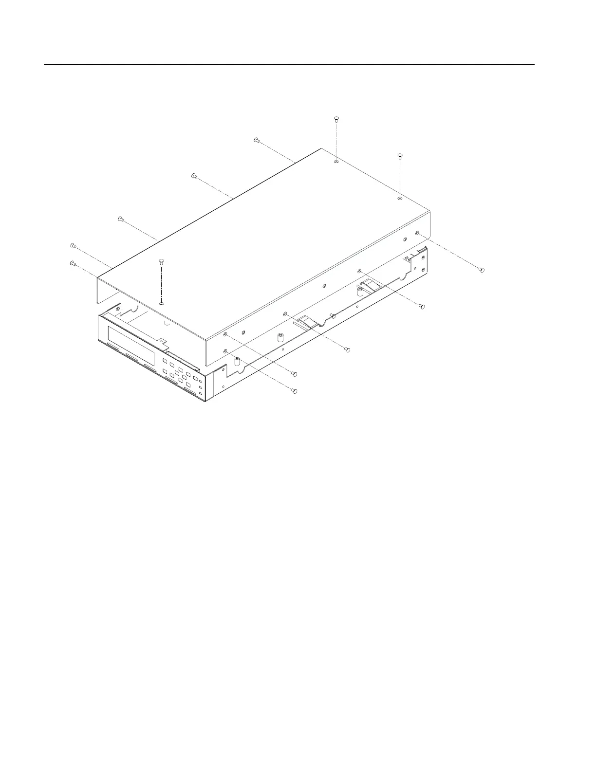
Figure 6-13: Top cover removal (SPG300)
Front-Panel Assembly
1. Locate module to be removed: Locate the front-panel assembly in the locator
diagram SPG300 External modules, Figure 6-4, on page 6-10.
2. Orient instrument: Set the SPG300 so its bottom is down on the work surface
and its front is facing you.
3. Remove the front chassis: See Figure 6-14.
a. Use a screwdriver with a #2 Phillips tip to remove the screw securing the
front chassis to the main chassis
b. Lift it away from the main chassis.
4. Remove the LCD module: See Figure 6-14.
a. Use a screwdriver with a #2 Phillips tip to remove the four screws securing
the LCD module to the front chassis.
b. Unplug the cable from the A50 Main board.
 Loading...


