Removal and Installation Procedures
6-28 SPG600 & SPG300 Sync Pulse Generators Service Manual
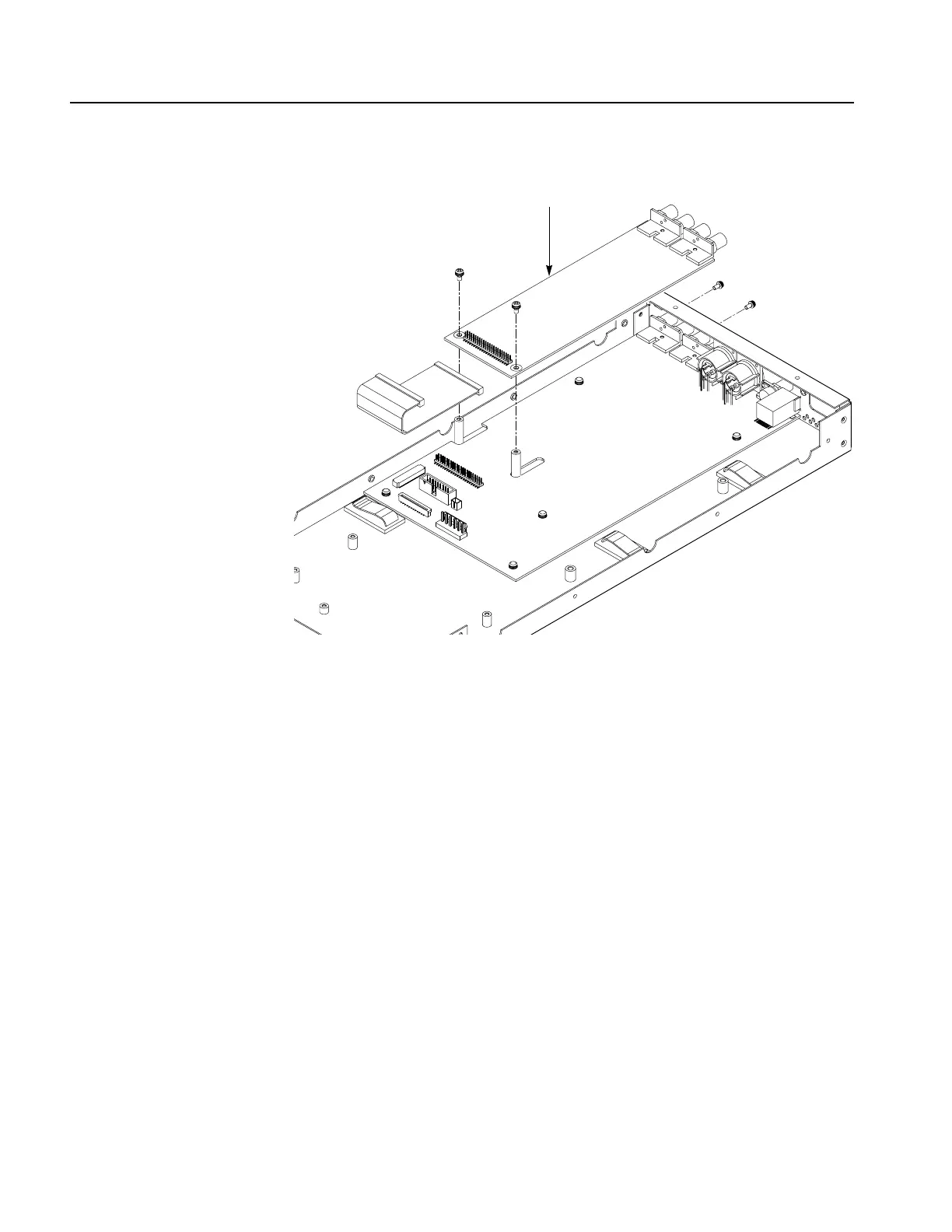
Figure 6-15: A60 Analog board removal
A50 Main Board
1. Locate module to be removed: Locate the A50 Main board in the locator
diagram SPG300 Internal modules, Figure 6-5, on page 6-11.
2. Orient the instrument: Set the SPG300 so its bottom is down on the work
surface and its right side is facing you.
3. Remove the A50 Main board: See Figure 6-16.
a. Unplug these cables:
The cable from the LCD module at J000.
The cable from the A20 Front-panel board at J010.
The cable from the fan at J3.
The cable from the power supply at J900.
The cable from the GPI connector at J100.
b. Use a screwdriver with a #1 Phillips tip to remove the seven screws
securing the A50 Main board to the rear of the chassis.
A50 Main board
A60 Analog board
J600
 Loading...


