Performance Verification
4-20 SPG600 & SPG300 Sync Pulse Generators Service Manual
11. On the digital audio monitor front panel, press the AUDIO button to display
Audio/Session view.
12. Verify that the digital audio monitor bar graphs show both Channel 1 and
Channel 2 at -20 dBFS.
13. Change the XLR cable connection from the 1+2/RIGHT connector to the
3+4/LEFT connector on the sync pulse generator.
14. Repeat step 12.
XLR Analog Audio Outputs
This test verifies that analog audio signals are output correctly from the
1+2/RIGHT and 3+4/LEFT XLR connectors. The following equipment is required
for this test:
Video measurement set
Two female XLR to male mini-XLR adapter cables
Perform the following procedure to verify that analog audio signals are output
correctly from the 1+2/RIGHT and 3+4/LEFT XLR connectors.
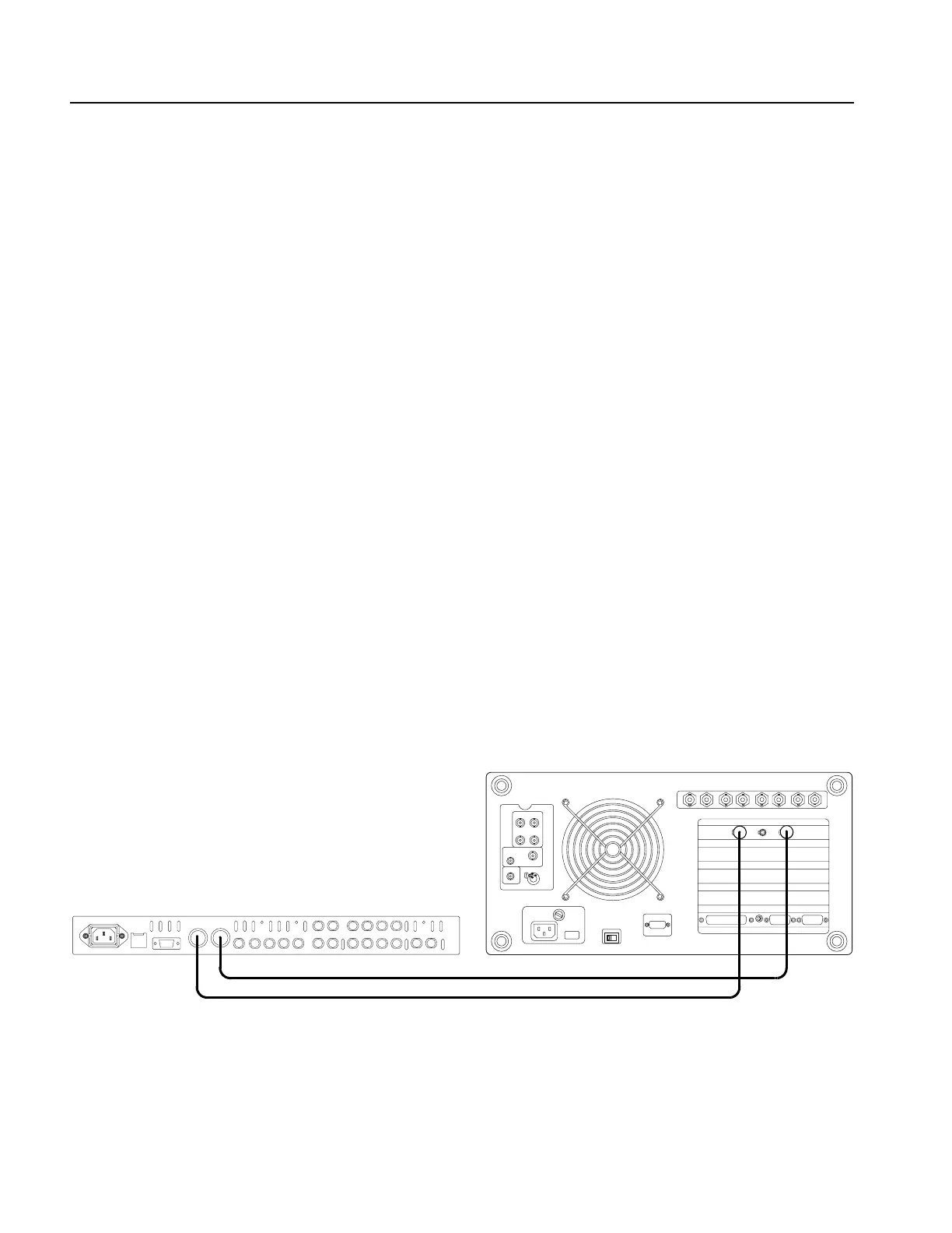
1. Use the female XLR to male mini-XLR adapter cable to connect the
1+2/RIGHT connector on the sync pulse generator to the RIGHT INPUT
connector on the video measurement set. See Figure 4-8.
2. Use the female XLR to male mini-XLR adapter cable to connect the 3+4/LEFT
connector on the sync pulse generator to the LEFT INPUT connector on the
video measurement set. See Figure 4-8.
Figure 4-8: Equipment connection for verifying the XLR analog audio outputs
SPG600 rear panel
Video measurement set
rear panel (VM700T Option 01/11/1S/40)
Female XLR to male mini-XLR adapter cable
 Loading...


