Removal and Installation Procedures
SPG600 & SPG300 Sync Pulse Generators Service Manual 6-21
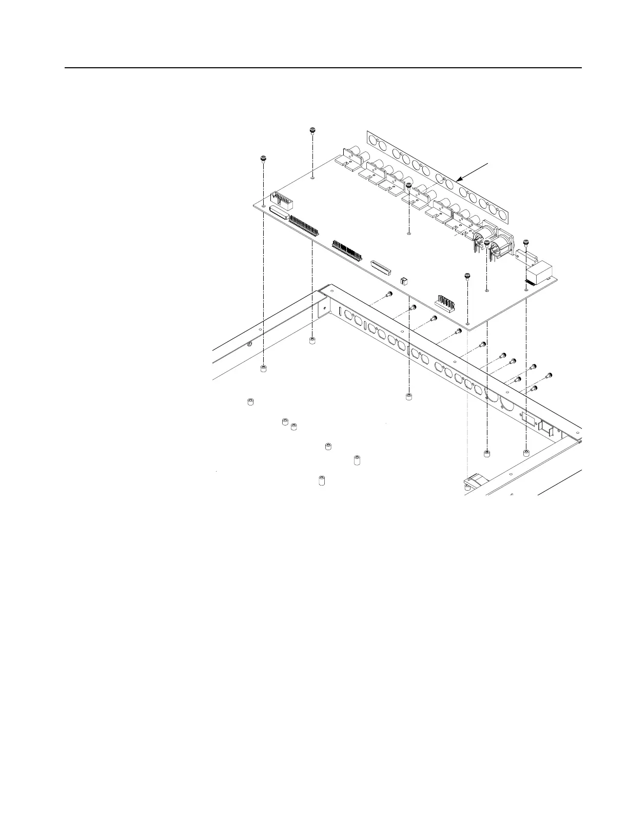
Figure 6-11: A10 Main board removal
Power Supply Module
This procedure describes how to remove these modules:
Fan
Power supply
1. Locate modules to be removed: Locate the fan and power supply module in the
locator diagram SPG600 Internal modules, Figure 6-3, on page 6-9.
2. Orient the instrument: Set the SPG600 so its bottom is down on the work
surface and its right side is facing you.
J010
Shield
J5
J000
J900
 Loading...


