Removal and Installation Procedures
6-12 SPG600 & SPG300 Sync Pulse Generators Service Manual
Access Procedure
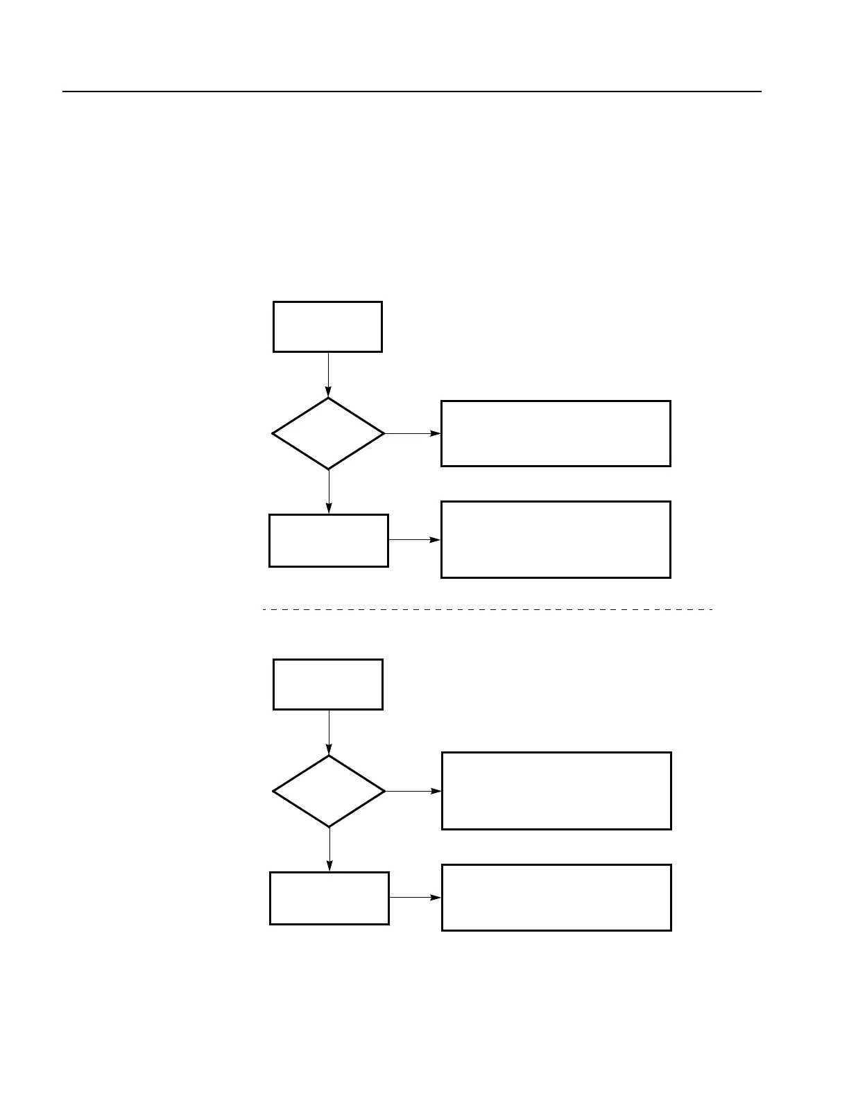
When you have identified the module to be removed for service, read General
Instructions found on page 6-6. Then use the flowchart in Figure 6-6 to determine
which procedures to use for removing the module. The removal procedures end
with installation instructions.
Figure 6-6: Guide to removal procedures
Locate the module to
be removed in
Figure 6-2 or 6-3.
Is the
module in
Figure
6-2?
Procedures for SPG600 External Modules
To p c o ve r p. 6 - 1 3
Front-panel assembly p.6-15
RFI filter p.6-16
Locate the module to
be removed in
Figure 6-3.
Yes
No
Procedures for SPG600 Internal Modules
A30 Analog board (Option 02) p.6-17
A40 SDI board (Option 03) p.6-18
A10 Main board p.6-20
Power Supply module p.6-21
SPG600
Locate the module to
be removed in
Figure 6-4 or 6-5.
Is the
module in
Figure
6-4?
Procedures for SPG300 External Modules
To p c o ve r p. 6 - 2 3
Front-panel assembly p.6-24
RFI filter p.6-26
GPI connector p.6-26
Locate the module to
be removed in
Figure 6-5.
Yes
No
Procedures for SPG300 Internal Modules
A60 Analog board p.6-27
A50 Main board p.6-28
Power Supply module p.6-30
SPG300
 Loading...


