CUTTING UNIT
4157082 First Edition 8-15
8
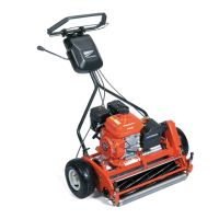
Figure 8-6
3. Loosen nuts (2) on both sides just enough to allow
knob (1) to raise the front roller or turf groomer. Raise
both sides an equal amount.
4. Set gauge screw (4) to the desired cutting height (5).
Measure from the gauge bar (6) to the underside of
the screw head (4), then tighten wing nut to lock the
adjustment.
5. Place gauge bar between front roller and traction
roller, near the outer end of the rollers.
6. Slide screw head over bedknife (3) and adjust knob
(1) so roller just contacts the gauge bar. Tighten nut
(2).
7. Repeat steps 5 and 6 on the opposite end of the reel,
then tighten nuts (2). Recheck and readjust the
cutting height if necessary.
Reel Bearing Pre-Load Adjustment
See Figures 8-7 through 8-9.
1. Park the mower safely. (See “Park Mower Safely” on
page 1-6.)
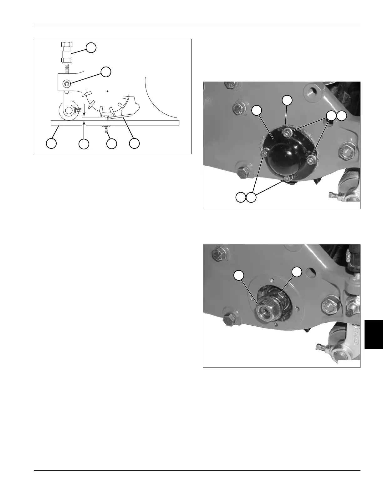
Figure 8-7
2. Remove four socket-head screws (3), lock washers
(4), reel cover (1), and gasket (2).
Figure 8-8
3. Tighten nut (5) until the spring (6) is completely
collapsed, then back the nut 2—3 turns, or until there
is 0.040 in. (1.27 mm) side-to-side movement of the
reel.
1
2
3
4
5
6
TN0011
TN0153
~
1
2
3
4
3
4
5
TN0154
6