4-12 4157082 First Edition
ELECTRICAL
4
6. Move the engine on/off switch to the OFF position
and check for continuity.
Is continuity indicated?
YES The switch is good.
NO The switch is faulty; replace the switch.
7. Install E-stop switch. (See “Component Removal and
Installation” on page 4-12.)
8. Install handle cover. (See “Handle Cover” on
page 6-2.)
Engine Components
Refer to the engine manual for testing of engine-related
electrical components.
Component Removal and
Installation
E-Stop Switch
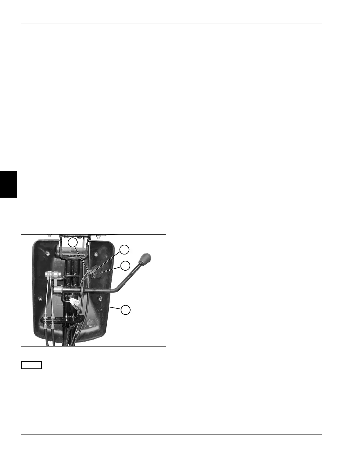
See Figure 4-8.
1. Park the mower safely. (See “Park Mower Safely” on
page 1-6.)
2. Remove the rear half of the handle cover. (See
“Handle Cover” on page 6-2.)
Figure 4-8
NOTE
Record the location of the wires before disconnecting.
3. Disconnect E-stop switch wires (1 and 2) and remove
the E-stop switch (3) from the front half of cover (4).
Installation Note
Install the E-stop switch by reversing the order of
removal.
TN0025
2
1
4
3