ACCESSORIES
4157082 First Edition 10-23
10
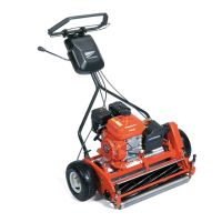
Figure 10-39
11. Install belt cover (20) using flat washers (18) and lock
nuts (19).
12. Install clutch control knob (17) using lock washers
(21) and hex head screws (22).
13. Install hex head screw (23) with lock washer (24).
14. Set height-of-cut. (See “Height-of-Cut Adjustment”
on page 8-14.)
15. Set turf groomer height-of-cut. (See “Turf Groomer
Height-of-Cut Adjustment” on page 10-7.)
Driven Assembly
Removal
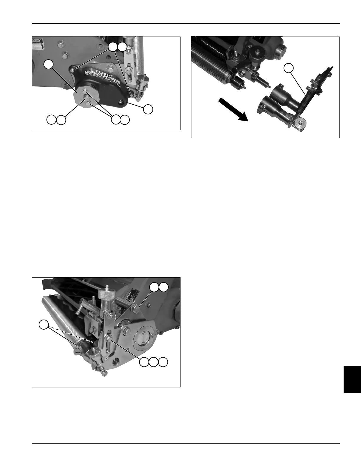
See Figures 10-40 through 10-41.
1. Park the mower safely. (See “Park Mower Safely” on
page 1-6.)
Figure 10-40
2. Loosen turf groomer and roller shaft set screws (1).
3. Remove hex head screw (2) and lock washer (3).
4. Remove hex head screw (4), lock washer (5), and
spacer (6).
Figure 10-41
5. Remove driven assembly (7) from machine.
TN0311
21
24
17
18
20
22
23
19
TN0329
2
1
3
654
7
TN0330