HANDLE AND CONTROLS
4157082 First Edition 6-7
6
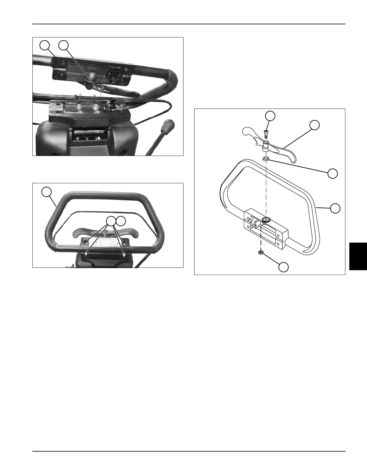
Figure 6-19
3. Connect throttle cable (8) to handle (7)
Figure 6-20
4. Install handle (9) on tilt plate, using four socket-head
screws (10) and four nuts (11).
Throttle Paddle
Removal and Installation
See Figure 6-21.
1. Park the mower safely. (See “Park Mower Safely” on
page 1-6.)
2. Remove handle cover. (See “Handle and OPC Bail”
on page 6-6.)
Figure 6-21
3. Remove nut (5), socket-head screw (1), throttle
paddle (2), and spring washer (3) from handle cover
(4).
Installation Note
Install throttle paddle by reversing the order of removal.
8
TN0060
7
TN0059
10 11
9
5
TN0063
4
3
1
2