SPECIFICATIONS AND GENERAL INFORMATION
4157082 First Edition 2-3
2
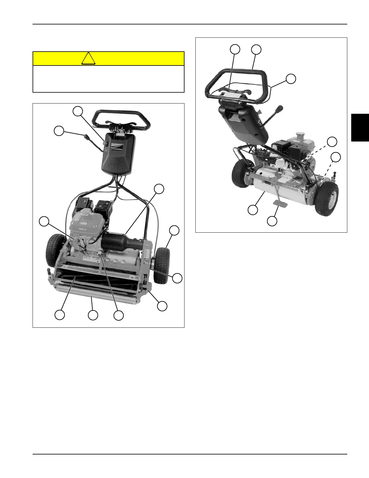
Component Location
!
CAUTION
Figure 2-3: Component Location—Front
Figure 2-4: Component Location—Rear
Become familiar with operator controls, machine
components, and correct operating procedures
before beginning repair procedures.
1 Park Brake Lever
2E-stop Switch
3Clutch Cover
4 Transport Wheels
(Optional)
5Chain Cover
6 Reel Clutch Lever
7 Engine Oil Dipstick
8Roller
9Reel
10 Engine On/Off Switch
1
2
3
4
5
6
10
9
8
7
TN0003
1 Throttle Paddle
2 Handle
3OPC Bail Lever
4 Fuel Shutoff and Choke
Control
5 Product Identification Plate
6 Kickstand
7 Traction Drum
5
1
2
3
7
6
4
TN0004