6-8 4157082 First Edition
HANDLE AND CONTROLS
6
Brake Control Lever
Removal
See Figures 6-22 and 6-23.
1. Park the mower safely. (See “Park Mower Safely” on
page 1-6.)
2. Release park brake.
3. Remove rear half of handle cover. (See “Handle
Cover” on page 6-2.)
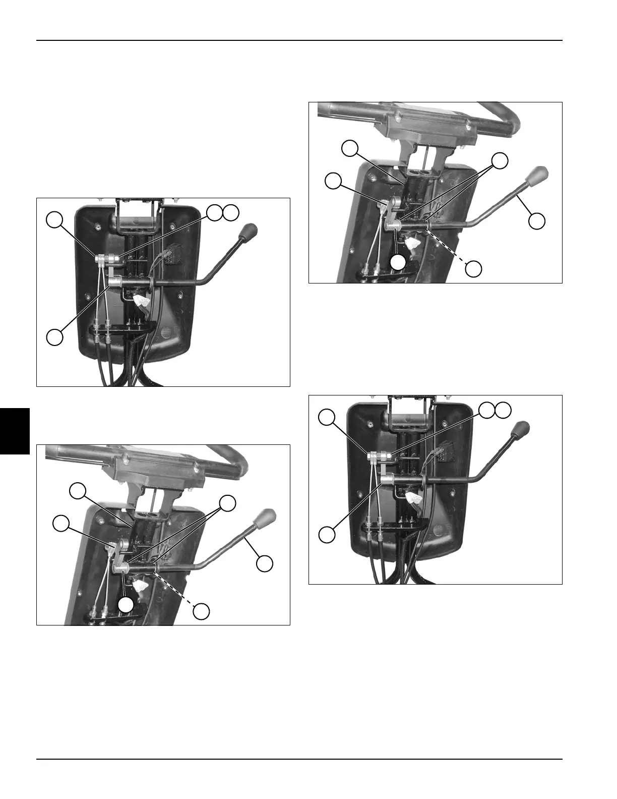
Figure 6-22
4. Remove nut (2), lock washer (3), and screw (1) from
brake lever arm (4).
Figure 6-23
5. Using a punch, drive out pin (9) and remove brake
lever arm (10).
6. Slide brake lever (7) out of handle (5), and remove
spring washer (8).
7. Inspect flanged bearings (6). Replace as needed.
Installation
See Figures 6-24 and 6-25.
Figure 6-24
1. Install flanged bearings (2) in handle (1).
2. Install spring washer (4) over end of brake lever (3),
and install lever into flanged bearings (2).
3. Install brake lever arm (6) onto brake lever shaft, and
secure by driving a pin (5) through lever arm and
shaft.
Figure 6-25
4. Install screw (7) on lever arm (10) using a lock
washer (8) and nut (9).
5. Check and adjust park brake as needed. (See “Park
Brake Check and Adjustment” on page 7-4.)
6. Install rear half of handle cover. (See “Handle Cover”
on page 6-2.)
TN0026
1
2 3
4
TN0047
10
9
7
6
8
5
TN0047
6
5
3
2
4
1
TN0026
7
8 9
10