HANDLE AND CONTROLS
4157082 First Edition 6-3
6
Installation
See Figures 6-4 and 6-5.
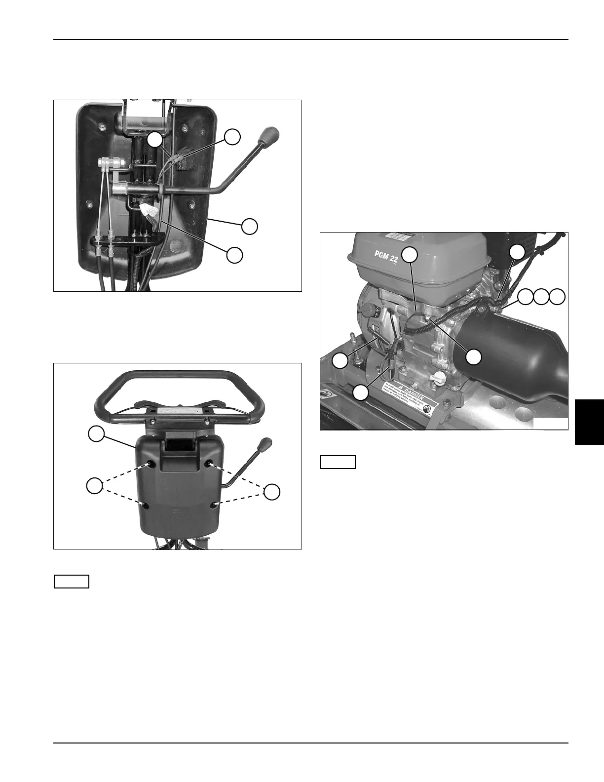
Figure 6-4
1. Route throttle cable (4) through hole at top of front
half of cover (3).
2. Connect wires (1 and 2) to E-stop switch.
Figure 6-5
NOTE
Align park brake cables with openings in covers before
tightening cover screws.
3. Install rear half of cover (5) to front half using four
socket-head screws (6).
4. Install throttle cable. (See “Throttle Cable” on
page 3-5.)
5. Adjust throttle cable. (See “Throttle and Clutch
Control Cable Adjustment” on page 3-4.)
Handle Assembly
Removal
See Figures 6-6 through 6-9.
1. Park the mower safely. (See “Park Mower Safely” on
page 1-6.)
2. Disconnect throttle cable at engine throttle plate.
(See “Throttle Cable” on page 3-5.)
3. Disconnect clutch cable at engine throttle plate. (See
“Clutch Control Cable” on page 5-4.)
4. Disconnect both park brake cables at brake bands.
(See “Park Brake Cable” on page 7-5.)
Figure 6-6
NOTE
Label all wires before disconnecting to ensure correct
installation.
5. Remove nut (6) and disconnect ground wire (1).
6. Disconnect engine on/off switch wire (8).
7. Disconnect engine harness wire (7).
8. Remove screw (3), lock washer (4), flat washer (5),
and clamp (2) from engine.
4
TN0025
2
1
3
6
TN0024
5
6
TN0032
2
3 4 5
1
6
8
7