6-4 4157082 First Edition
HANDLE AND CONTROLS
6
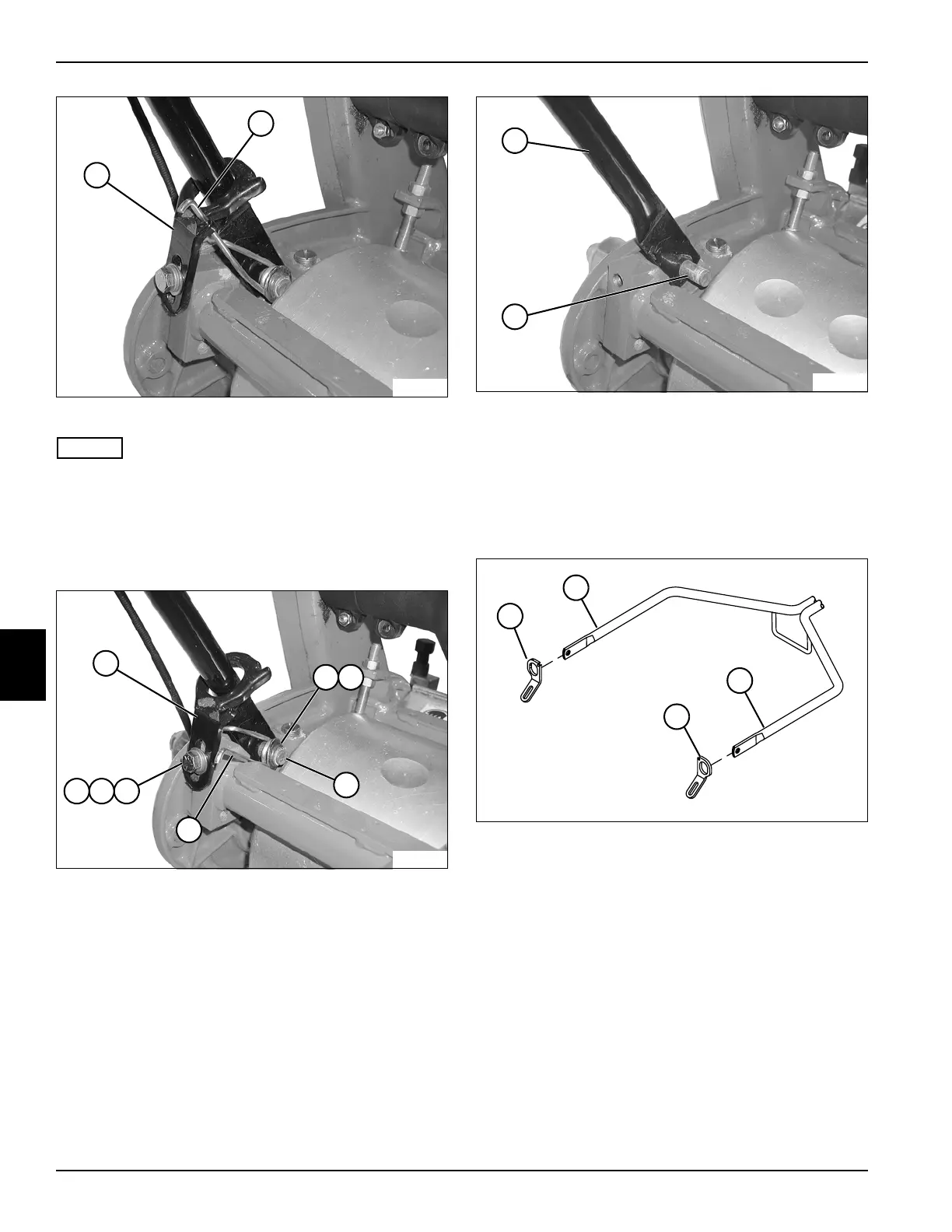
Figure 6-7
NOTES
• Support handle assembly before removing mounting
hardware.
• Steps 9 through 11 apply to both sides of handle
assembly.
9. Disconnect torsion spring (10) from handle stop (9).
Figure 6-8
10. Remove screw (16), lock washer (17), and washer
(18) from handle stop (11).
11. Remove retaining ring (12), washer (13), and torsion
spring (15) from stud (14).
Figure 6-9
12. Remove handle assembly, by pressing in on handle
tube (19) until end of tube clears stud (20). Slide
other side off other stud.
Installation
See Figures 6-10 through 6-14.
Figure 6-10
1. Slide right (1) and left (4) handle stops over handle
tubes (2 and 3).
9
TN0033
10
17
TN0034
16
12
11
15
14
13
18
19
TN0036
20
TN0062
2
1
3
4