HANDLE AND CONTROLS
4157082 First Edition 6-5
6
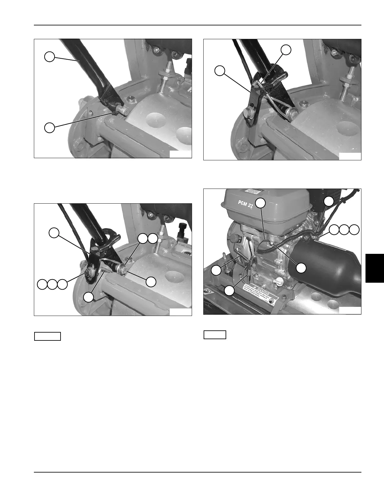
Figure 6-11
2. Slide one handle tube (5) onto stud (6). Press other
handle tube in until end of tube slips over end of stud.
3. Support handle assembly.
Figure 6-12
NOTES
• Support handle assembly until mounting hardware is
installed.
• Steps 4 through 6 apply to both sides of the handle
assembly.
4. Install torsion spring (11), washer (8), and retaining
ring (9) on stud (10).
5. Secure handle stop (7) to frame using screw (12),
lock washer (13), and washer (14).
Figure 6-13
6. Connect torsion spring (16) to handle stop (15).
Figure 6-14
NOTE
Connect wires to same connector as noted during
removal.
7. Install ground wire (17) to stud using nut (22).
8. Connect wire (24) to engine on/off switch.
9. Connect wire (23) to engine harness connector.
10. Install clamp (18) to engine using a screw (19), lock
washer (20), and flat washer (21).
11. Connect throttle cable to engine throttle plate. (See
“Throttle Cable” on page 3-5.)
12. Connect clutch cable to engine throttle plate. (See
“Clutch Control Cable” on page 5-4.)
13. Connect both park brake cables to brake bands. (See
“Park Brake Cable” on page 7-5.)
5
TN0036
6
13
TN0034
12
8
7
11
10
9
14
15
TN0033
16
TN0032
18
19 20 21
17
22
24
23