ELECTRICAL
4157082 First Edition 4-11
4
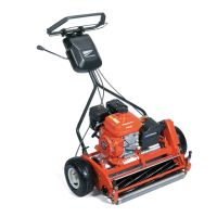
Engine On/Off Switch
See Figures 4-5 and 4-6.
1. Park the mower safely. (See “Park Mower Safely” on
page 1-6.)
Figure 4-5
2. Disconnect engine on/off switch wire (1).
3. Remove the blower housing from the engine. (Refer
to engine manual.)
Figure 4-6
4. Connect test leads between engine on/off switch wire
(2) and grounding tab (3).
5. Move engine on/off switch to the ON position and
check for continuity.
Is continuity indicated?
YES The switch is faulty; replace the switch.
NO Proceed to Step 6.
6. Move engine on/off switch to the OFF position and
check for continuity.
Is continuity indicated?
YES The switch is good.
NO The switch is faulty; replace the switch.
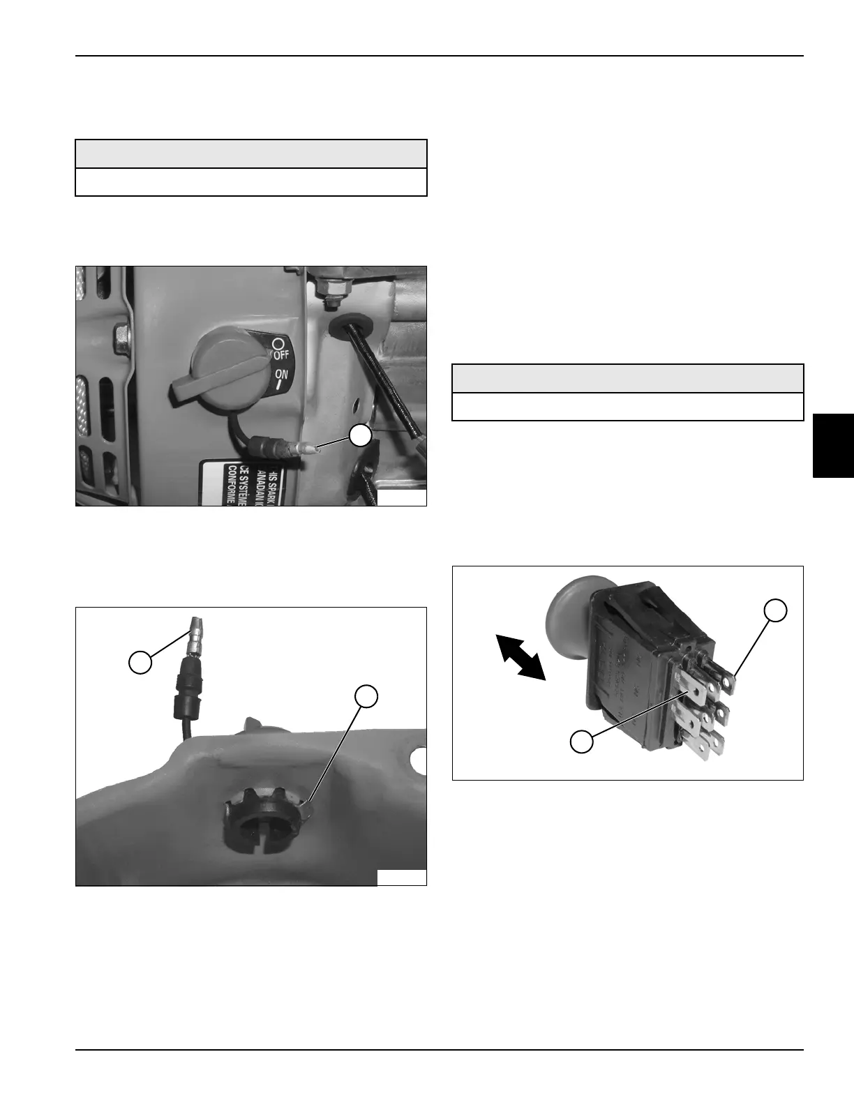
E-Stop Switch
See Figure 4-7.
1. Park the mower safely. (See “Park Mower Safely” on
page 1-6.)
2. Remove the rear half of the handle cover. (See
“Handle Cover” on page 6-2.)
3. Remove E-stop switch. (See “Component Removal
and Installation” on page 4-12.)
Figure 4-7
4. Connect test leads to the COM C (1) and NC (2)
switch terminals (1 and 2).
5. Move the engine on/off switch to the ON position and
check for continuity.
Is continuity indicated?
YES The switch is faulty; replace the switch.
NO Proceed to Step 6.
Required Tools or Equipment
Digital Multimeter, Ohmmeter, or Continuity Tester
TN0139
1
3
TN0138
2
Required Tools or Equipment
Digital Multimeter, Ohmmeter, or Continuity Tester
TN0142
2
1
ON
OFF