Drawings
1
10
11
12
13
2
3
4
5
6
7
8
9
14
15
16
10U F
10U F
VA+5
0.1 UF0.1 UF0.1 UF
0.1 UF 0.1 UF 0.1 UF
MUXA0
MUXA1
MUXA2
S3
S4
S5
S6
S1
S2
V_DE T
0.1 UF
DGN D
10U F 0.1 UF 0.1 UF 0.1 UF
VC C
AGN D
VA- 10_
CON16
+
Tantalum
+
Tantalum
+
Tantalum
G10 DETECTOR BOARD
335901-603-1
REV. A
U5^4
U5^7U7^16U6^14
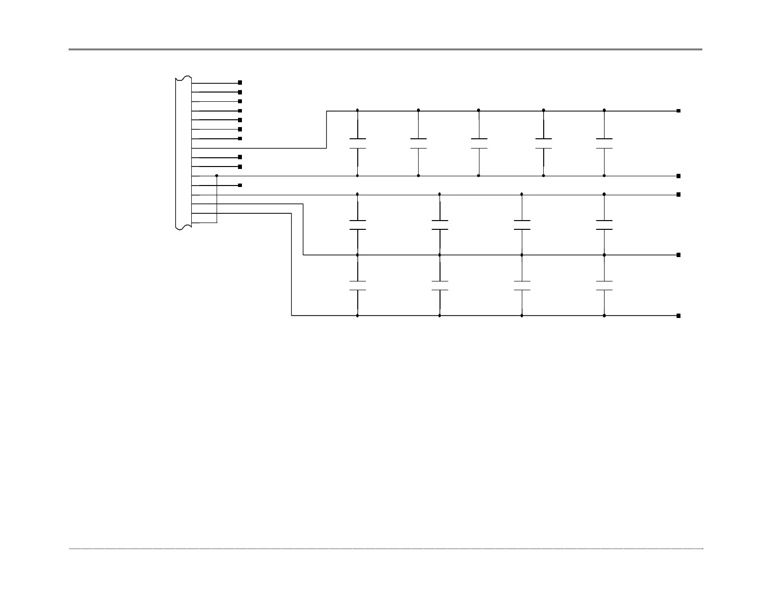
NOTE S
USE 8 MIL TRACE FOR ALL OTHER SIGNALS
2. PLACE 0.1UF DECOUPLING CAPACITORS (C7-C16) CLOSE TO POWER AND GROUND PINS OF ICs.
1. PLACE 10UF DECOUPLING CAPACITORS (C1-C3) CLOSE TO CONNECTOR (J1).
U1^2 U2^2 U3^2 U4^2
U7^8
IV C102 CD 40 51 O P177
U6^9 U7^7
3. USE 25 MIL TRACE TO RUN SIGNALS VCC, DGND, VA+5, AGND, AND VA-10_5.
SHEET 3 OF 3
C1 C7 C14 C15 C16
C2 C8 C10 C12
C3 C11 C13C9
Figure 8.21 Spectronic GENESYS 10 Detector board 3 of 3
8-43
 Loading...


