Disassembly and Replacement
1. Attach each of the bottom and edge cable connectors to their appropriate position on the Main
Circuit board.
2. Carefully position the board in its mounting location. Make sure the mounting holes in the board
line up with the mounting holes in the base. Carefully route the ribbon cables as necessary to make
sure they will not be damaged when the covers are replaced, or pinched under the board.
3. Insert and tighten the seven mounting screws.
4. Turn the unit over and attach the remainder of the wire connectors to the top and end of the Main
Circuit board.
5. If the firmware revision of the new board is ≤ 1.030, then replace the ROM and flash it to the
current version. If the firmware revision of the new board is > 1.030, then the firmware must flashed
into the ROM (see the instructions for GenFlash). Recalibrate the instrument.
Front Panel Assemblies
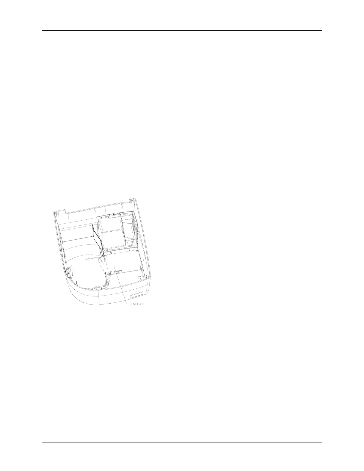
Display
Figure 5.22 Display Location in Top cover
Removal
1. Remove the top cover (refer to “Top Cover").
2. Disconnect the cable for the display.
3. Remove the four screws holding the display to the top cover and set aside.
4. Carefully lift the display from the top cover.
5-25
 Loading...


