Disassembly and Replacement
Grating motor Block assembly Spectronic GENESYS 6/Spectronic GENESYS 10 UVscanning
(335908-135S)
Removal
1. Remove the grating assembly (refer to “Grating assembly”).
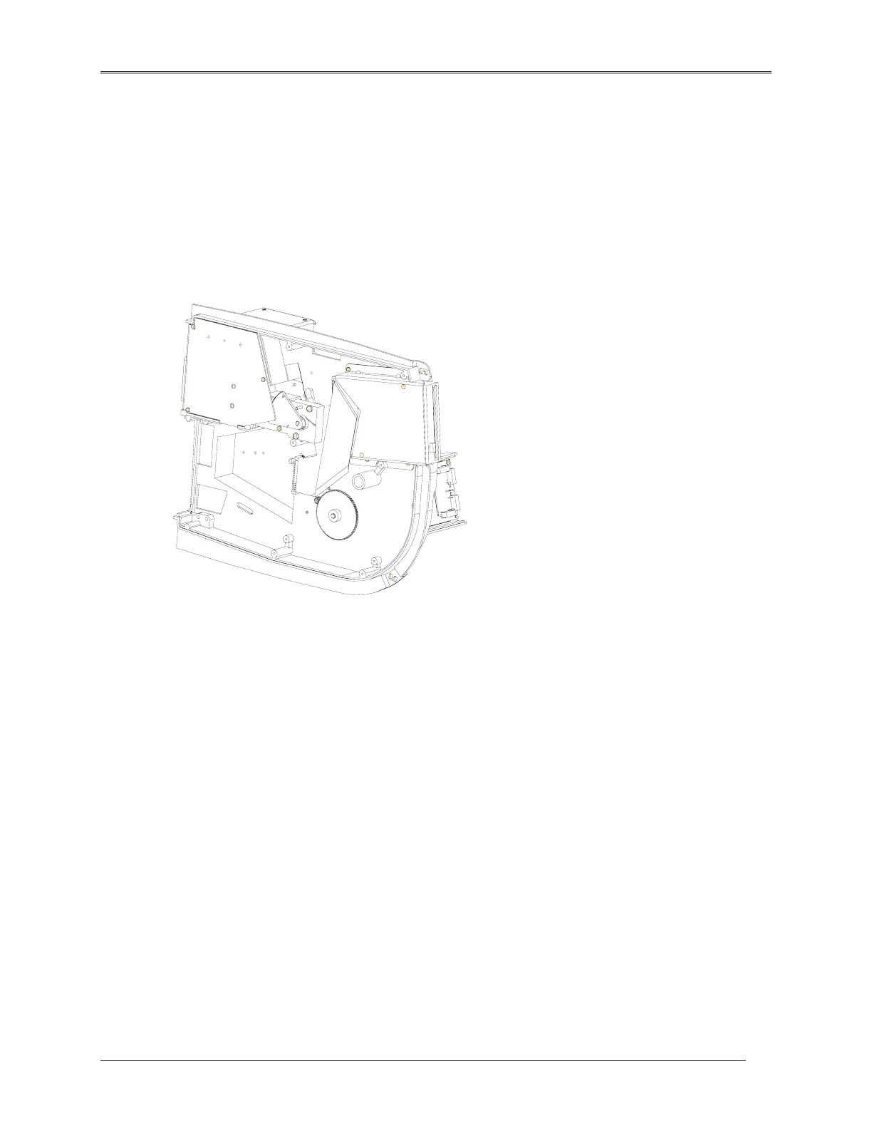
2. Turn the instrument on its side as shown and disconnect the wire connector for the grating motor
from the Main Circuit board.
Figure 5.20 grating motor block assembly, Power Supply, and Floppy Drive Location
3. From the bottom of the instrument, remove the three screws securing the Power Supply bracket to
the base. Leave the Power Supply bracket in place; it only needs to be loose enough to allow room
to remove the grating motor Block assembly.
4. Remove the two 8-32 screws that secure the grating motor block assembly to the base.
5. Carefully remove the grating motor Block assembly so the shaft comes out of the base and set the
motor aside.
Replacement
1. From the bottom of the unit, insert the shaft of the grating motor Block assembly through the hole in
the base and turn the grating motor Block assembly so it’s mounting holes are aligned with the
mounting holes in the base.
2. Insert and tighten the two 8-32 screws used to secure the grating motor Block assembly to the
base.
3. Attach the wire connector for the grating motor wires to the Main Circuit board.
5-22
 Loading...


