Disassembly and Replacement
3. Position the ground wire over its mounting hole and insert and tighten the mounting screw.
4. Attach the wire connector to the top of the Main Circuit board.
Main (CPU) Circuit board (335901-6024S [UV-Vis Only]; 335901-6064S [Vis Only])
CAUTION: CIRCUIT BOARDS AND OTHER ELECTRONIC COMPONENTS ARE
SUBJECT TO DAMAGE FROM ELECTROSTATIC DISCHARGE. TO
PREVENT SUCH DAMAGE, USE A WRIST OR HEEL GROUNDING STRAP.
GROUND TOOLS THROUGH A CONDUCTIVE MAT BEFORE TOUCHING
ANY POTENTIALLY STATIC-SENSITIVE ASSEMBLIES OR DEVICES. WHEN
HANDLING PRINTED CIRCUIT BOARDS OR OTHER ELECTRONIC
ASSEMBLIES, HOLD THE BOARD BY ITS EDGES TO AVOID TOUCHING
CIRCUIT TRACES OR DEVICES WITH BARE HANDS OR FINGERS.
Removal
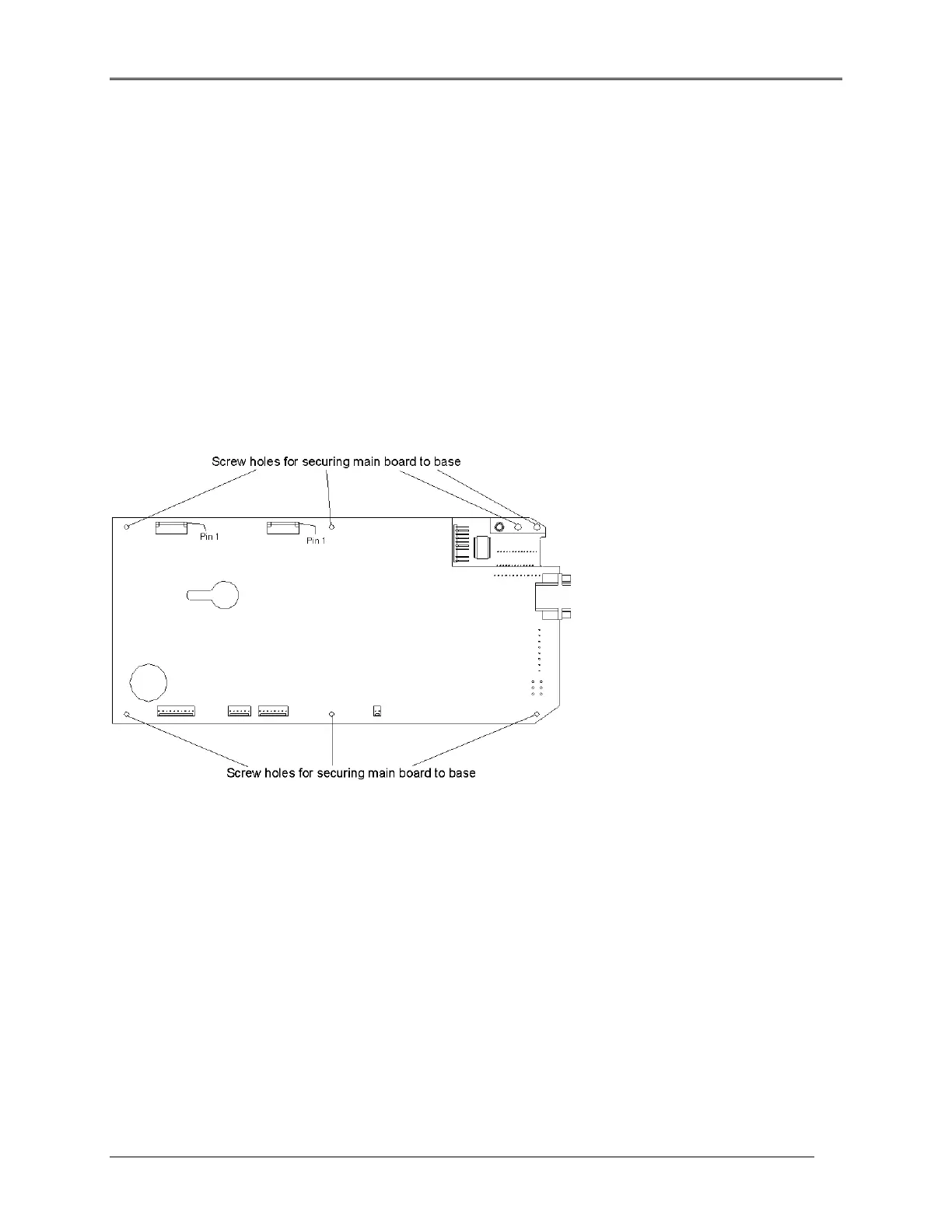
Figure 5.21 Main Circuit board Connector Locations
1. Disconnect all wire connectors on the top and end of the Main Circuit board, accessible at the rear
of the instrument through holes in the base casting.
2. Turn the instrument over and remove the seven screws attaching the board to the base.
3. Note how the ribbon cables are routed around the instrument standoffs.
4. Carefully lift the Circuit board away from the base and disconnect the balance of the wire
connectors.
Replacement
5-24
 Loading...


