Disassembly and Replacement
NOTE: Orient the ribbon cable so that the striped (non-conductive) side of the cable connector is
facing the Circuit board.
NOTE: Ensure that the end of the cable is inserted all the way into the connector. No part of the
exposed leads should be visible when the cable is locked into the connector.
6. Position the Circuit board in its mounting position making sure the holes on the Circuit board fit
over the two dowel pins.
7. Replace and tighten the two mounting screws.
8. Replace the Sample Detector cover.
9. Position the cover over the Sample Detector Circuit board and lens.
10. Insert and tighten the lower screw and the one upper screw, which is not common to the Beam
Splitter and turret cover.
11. After all replacements are complete for mirrors, light source, grating, and lenses, follow the optical
alignment procedures in “Optical Alignment."
12. When all other work is complete, replace the Beam Splitter and turret cover (refer to “Beam splitter
and turret cover ").
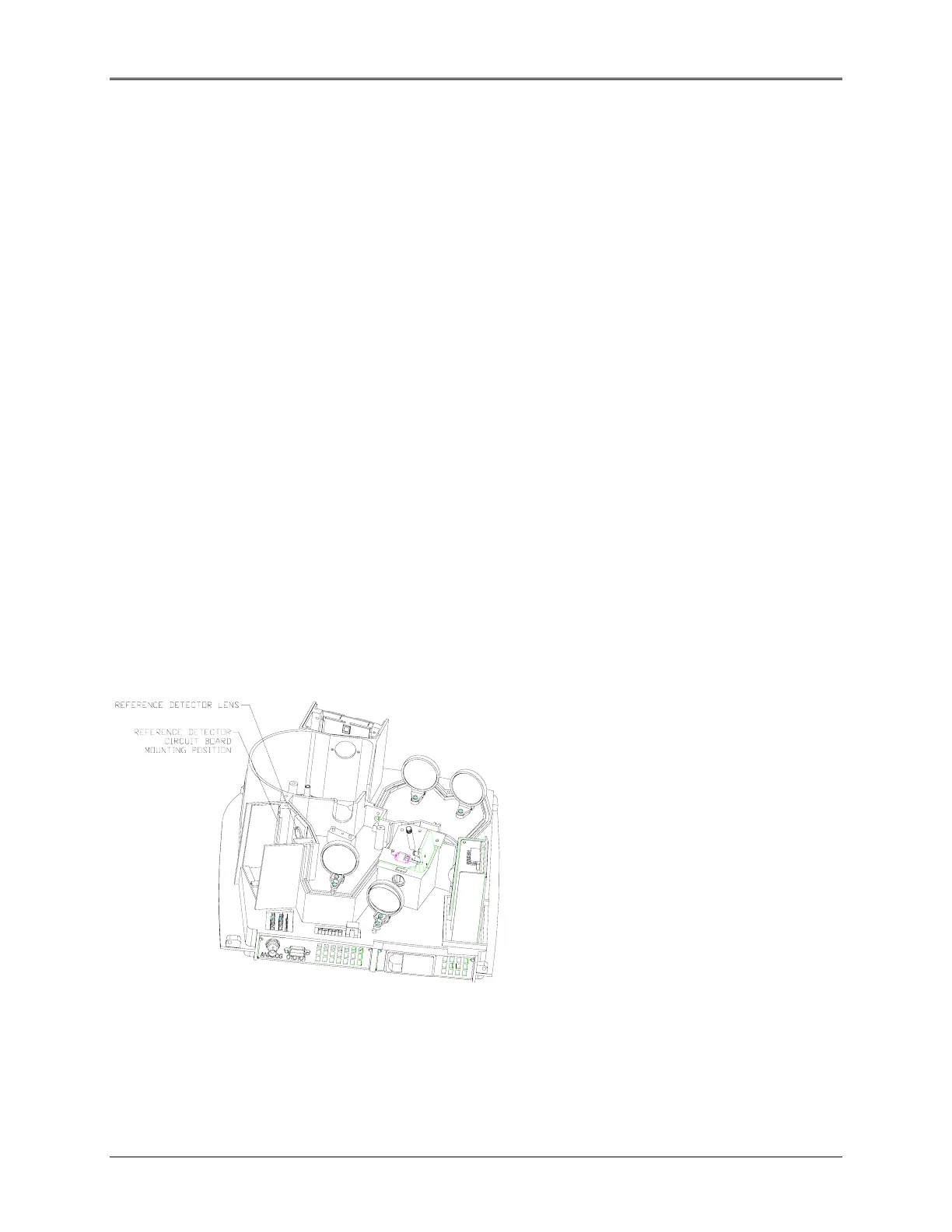
Reference Detector (335901-6034 [UV Only])
Removal
1. Remove the Beam Splitter and turret cover (refer to “Beam Splitter and turret cover").
Figure 5.14 Reference Detector Location
2. Remove the Reference Detector cover.
3. Remove the two screws securing the top of the Reference Detector cover.
5-13
 Loading...


