Routine Maintenance
Changing the fuse
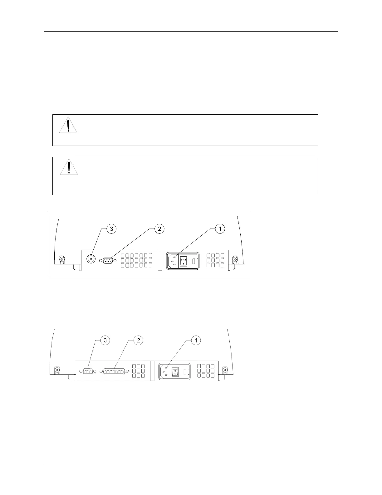
The fuse is located in the power entry module located at the center of the back panel of the instrument
(#1, Figure 4.2).
• 120VAC, 2.5A, Slo-Blo (2 required)
• 240VAC, 1.25A, Slo-Blo (2 required)
WARNING
The instrument fuse must be replaced with the same type and rating fuse.
WARNING
If the fuse fails repeatedly, it may indicate a serious problem with the instrument. Contact
technical support as soon as possible.
Figure 4.2a Back Panel of the Spectronic GENESYS 10 Spectrophotometer
Key
A/C power connector
RS232C port
Analog/BNC connector (optional)
Figure 4.2b Back Panel of the Spectronic GENESYS 10 UVscanning and
Spectronic GENESYS 6 Spectrophotometer
Key
A/C power connector
Parallel printer port
RS232C port
4-5
 Loading...


