Disassembly and Replacement
4. Replace the Reference Detector Circuit board.
5. Insert the ribbon cable into its connector making sure the No. 1 wire on the cable is at the No. 1
position on the connector and lock the connector.
NOTE: Orient the ribbon cable so that the striped (non-conductive) side of the cable connector is
facing the Circuit board.
NOTE: Ensure that the end of the cable is inserted all the way into the connector. No part of the
exposed leads should be visible when the cable is locked into the connector.
6. Position the Circuit board in its mounting position making sure the holes on the Circuit board fit
over the two dowel pins.
7. Replace and tighten the two mounting screws.
8. Replace the Reference Detector cover.
9. Position the cover over the Reference Detector Circuit board and lens.
10. Insert and tighten the three screws to secure the cover.
11. After all replacements are complete for mirrors, light source, grating, and lenses, follow the optical
alignment procedures in “Optical Alignment."
12. When all other work is complete, replace the Beam Splitter and turret cover (refer to “Beam splitter
and turret cover ").
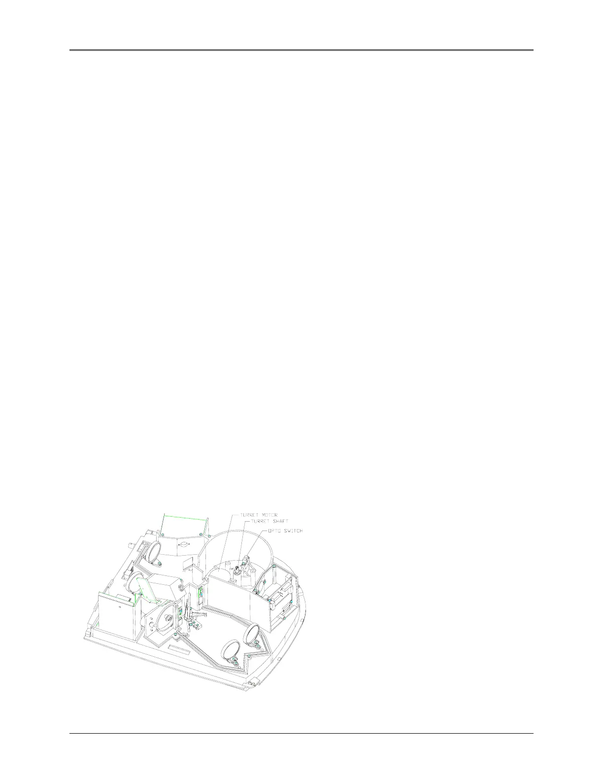
Turret motor (335901-660S [UV and Vis])
NOTE: The Opto switch, turret motor, and turret Shaft may each be removed independently
without removing the other two items, if so desired.
Removal
Figure 5.15 turret Components
5-15
 Loading...


