Disassembly and Replacement
1. Remove the Beam Splitter and turret cover (refer to “Beam splitter and turret cover ").
2. Remove the turret Opto Switch.
3. Turn the unit over and unplug the connector for the Opto switch /turret motor from the Main Circuit
board.
4. From the top side, remove the two screws, which secure the turret Opto Switch to the base.
5. Fit the wire connector up through the hole in the base being careful not to damage any of the other
wires passing through the hole and set the switch aside.
6. Remove the turret motor.
7. From the top, remove the two screws securing the turret motor to the base.
8. Pull the motor straight up through the hole in the base.
9. Fit the wire connector up through the hole in the base being careful not to damage any of the other
wires passing through the hole if not done in the previous step and set the motor aside.
10. Remove the Main Circuit board (refer to “Main board Connections").
11. Remove the turret shaft by looseing the set screw that holds the gear in place and removing the
gear. Lift the shaft out from the top of the instrument.
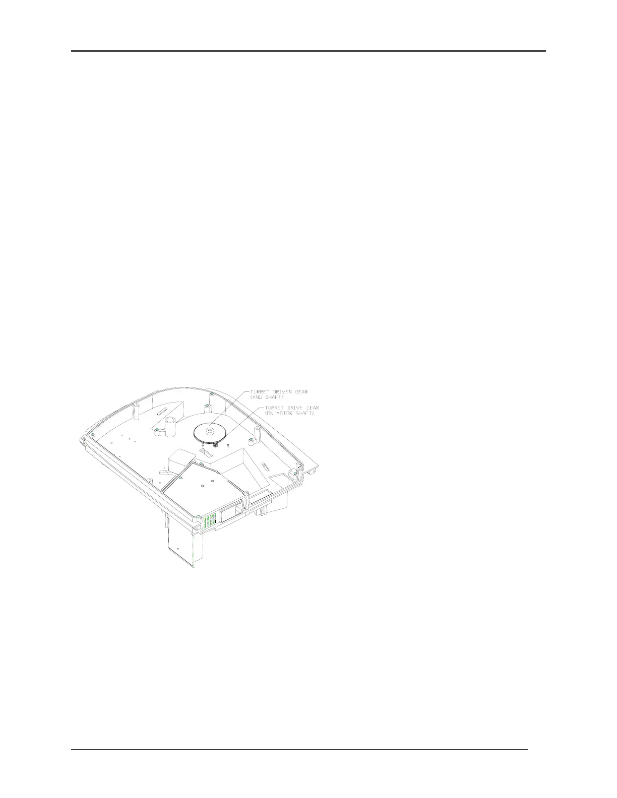
Figure 5.16 Bottom View Showing turret Gears
12. From the top, remove the E-clip securing the turret shaft in its bushing.
13. From the bottom, grasp the driven gear and carefully pull the shaft out through the bushing.
NOTE: On single cell units, the shaft is cemented in place and used as a guide only.
5-16
 Loading...


