Service Diagnostic Software
Capacitor or Voltage simply selects a different capacitor or resistor value to use in the feedback
loop.
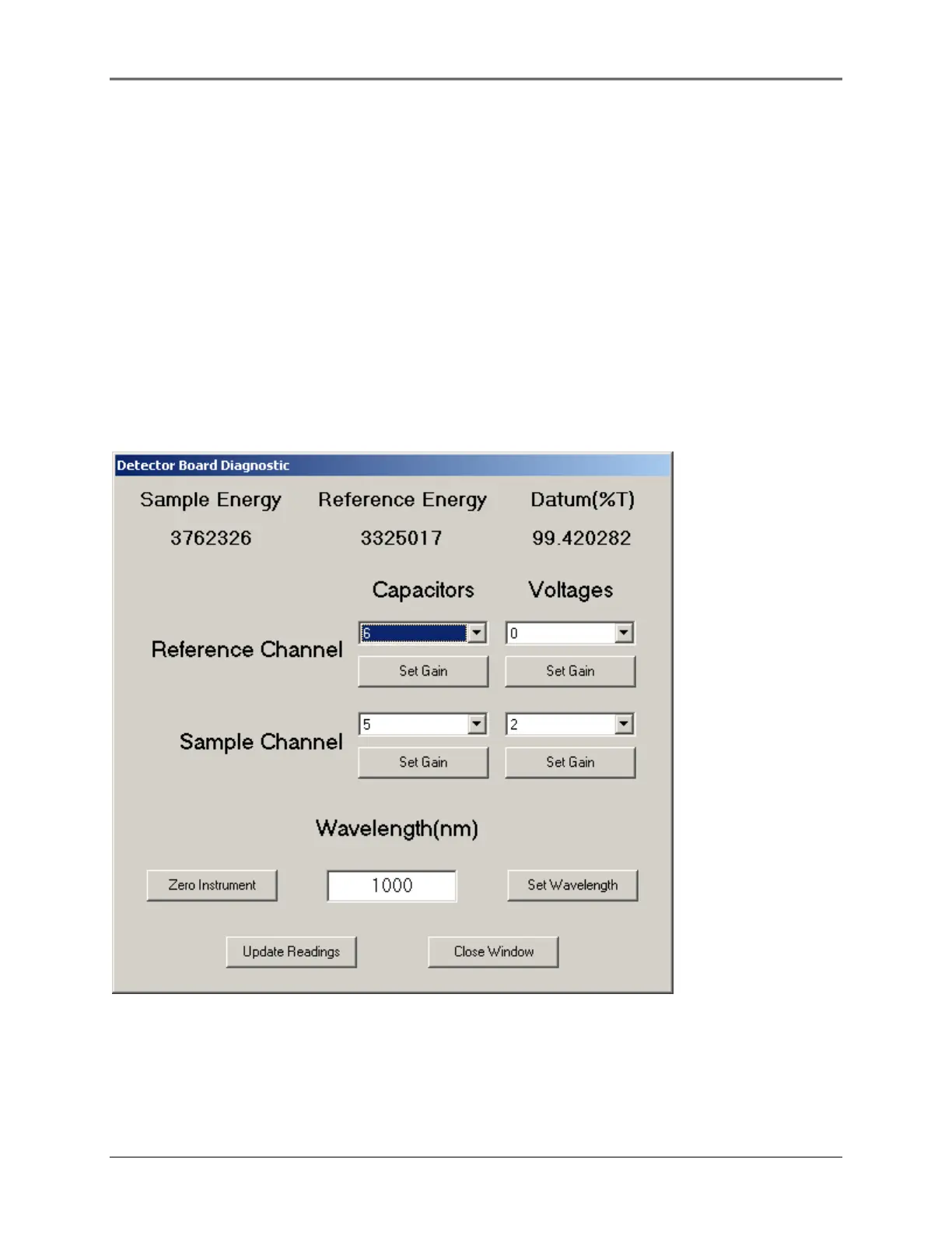
2. Use the Detector board Diagnostic screen to test for proper detector operation. The higher the gain
number, the higher the Energy level should be. The reading will saturate around 6,300,000 counts.
For each capacitor or resistor change there should be a corresponding change in the Sample
Energy or Reference Energy level. If there isn’t a corresponding change, and the reading isn’t
saturated, there is a problem with the Main board, detector, or ribbon cable. A simple way to test
the gain settings is to set the instrument wavelength to a low energy point, like 850nm and try each
gain setting.
3. Can be used when the covers have been removed, but the sample compartment must be covered
with a light-tight covering (black cloth).
4. Displays the energy levels of the Detector board(s).
5. For the UV model, the Sample Energy and the Reference Energy will be roughly equal, after the
instrument is zeroed (see examples on next page).
Figure 9.15 Detector board Diagnostic Window
6. The capacitor and voltage gains are the different resistor and capacitor selections. They are the
feedback components used as part of the integrator circuit used for the detector. A high value
results in a larger gain as shown in the gain tables.
9-10
 Loading...


