225 Programmable Hardware Manual (PHM)
© Tibbo Technology Inc.
RX/TX/CTS/RTS +
RX/TX + RX/tx
RX/TX/CTS/RTS +
RX/TX/CTS/rts
RX/TX/CTS/RTS +
RX/TX/DSR/dtr
RX/TX/DSR/DTR +
RX/TX + RX/tx
RX/TX/DSR/DTR +
RX/TX/CTS/rts
RX/TX/DSR/DTR +
RX/TX/DSR/dtr
RX/TX + RX/TX +
RX/TX + RX/tx
RX/TX/CTS/rts +
RX/TX + RX/TX
RX/TX/DSR/dtr +
RX/TX + RX/TX
RX/TX/CTS/RTS +
RX/tx/CTS/RTS
RX/TX/CTS/RTS +
RX/tx/DSR/DTR
RX/TX/DSR/DTR +
RX/tx/CTS/RTS
RX/TX/DSR/DTR +
RX/tx/DSR/DTR
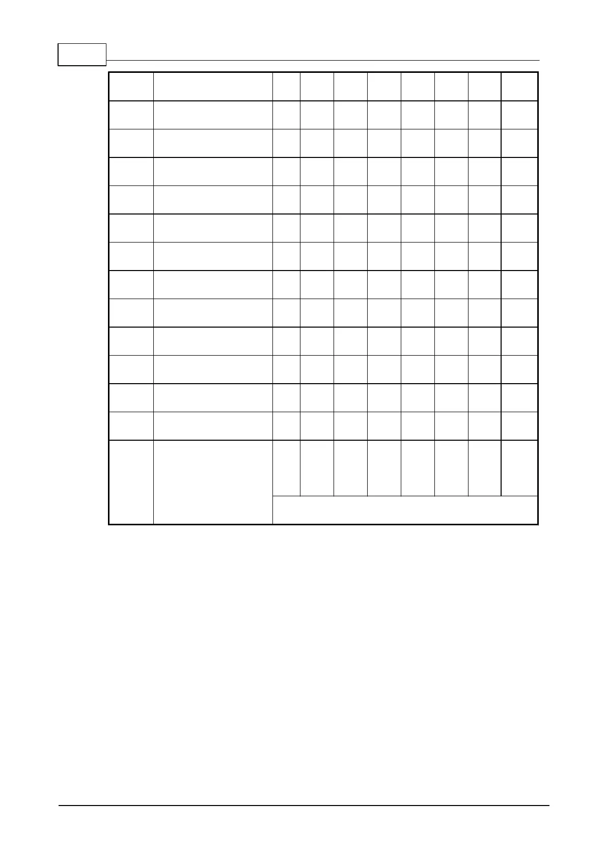
Terminal blocks of the expansion connector
(as marked on the EM1206EV)
"Available signals" column shows a particular combination of I/O lines for each
option. For example, option 0 defines the standard serial port arrangement with RX,
TX, CTS, RTS, DSR, and DTR lines. Option 2 gives you one channel with RX, TX,
CTS, and RTS lines, one more channel with just RX and TX lines, and yet another
channel with a single RX line. The TX line is "missing" because, once again, there are
only three outputs available on the RS232 port. This is why this line is shown in grey
lowercase (tx). This line, of course, is present and available on the expansion
connector.

 Loading...