E6582062
2. Installation and wiring 2-58
2
9
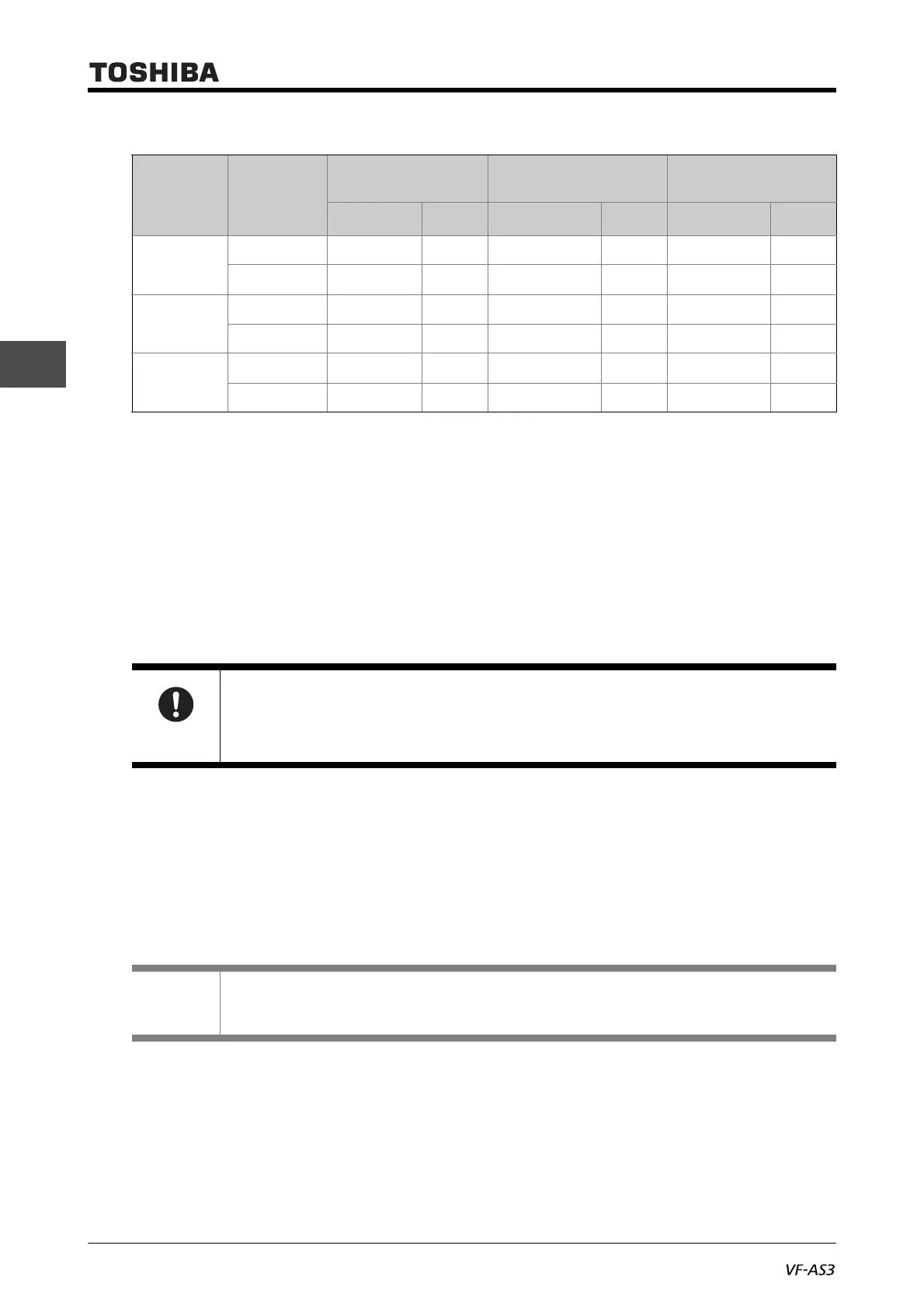
Wire size
■ Switching of slide switch of control terminal block
With the slide switch [SW1] of the control terminal block, the setting of sink logic, source logic and
external power supply sink logic of the digital input terminals [F], [R], [RES], and [S1] - [S5] is
switched.
For details of sink/source logic, refer to the following "■Sink logic and source logic."
• The slide switch [SW1] is set to the PLC side in the default setting. This is the setting when the
inverter external power supply is used
• To use as sink logic, set the slide switch [SW1] to the SINK side.
• To use as source logic, set the slide switch [SW1] to the SOURCE side.
■ Sink logic and source logic
In Japan and the U.S., current flowing out turns digital input terminals on. This is called sink logic.
The method generally used in Europe is source logic in which current flowing into digital input termi-
nals turns them on.
Each digital input terminal is supplied with electricity from either the inverter's internal power supply
or an external power supply, and its connections vary depending on the power supply used.
1) When the inverter internal power supply is used
When the internal power supply of the inverter is used to supply electricity to digital input termi-
nals, the connection is as shown in the diagram below.
Sink/source logic is set by the slide switch [SW1]. Refer to "■Switching of slide switch of control
terminal block."
Conductor
Using one wire Using two wires
Using two wires
with twin ferule
(mm
2
)
AWG
(mm
2
)
AWG
(mm
2
)
AWG
Relay
Solid wire 0.14-2.5 26-14 2x0.14 to 2x0.75 26-18 - -
Stranded wire 0.14-2.5 26-14 2x0.14 to 2x0.75 26-18 2x0.5 to 2x1.5 20-16
Except Relay
(2nd)
Solid wire 0.14-2.5 26-14 2x0.14 to 2x1.0 26-18 - -
Stranded wire 0.14-1.5 26-16 2x0.14 to 2x0.75 26-18 2x0.5 to 2x1.0 20-18
Except Relay
(1st)
Solid wire 0.14-1.5 26-16 2x0.14 to 2x0.75 26-18 - -
Stranded wire 0.14-1.5 26-16 2x0.14 to 2x0.75 26-18 2x0.5 to 2x1.0 20-18
Important
• Switch the logic before turning on the power supply.
• After confirming that the sink/source setting is correct, turn on the power supply.
Memo
• Sink logic is sometimes referred to as negative logic, and source logic is referred to as positive
logic.

 Loading...


