89
12 Interface
89
Interface
Chapter
12
e.g.) Status from Hold (address 10001) to OK output (address 10008) is read.
Note that the relative address is 0x00 when reading the hold value.
The F325 setting for this example is as follows.
The LSB of the first data is the status of the initial address.
00100000 (0x20) represented in binary digits.
* Status can also be read by function code 04 (0x04) Read Input Registers.
With function code 04, status is read along with the indicated value.
03 (0x03) Read Holding Registers
The contents of slave holding registers are read.
Broadcast cannot be specified.
The start address of the holding register and the number of registers are specified.
Slave devices transmit data by converting the contents of each register to 2 bytes.
*: N = Number of registers
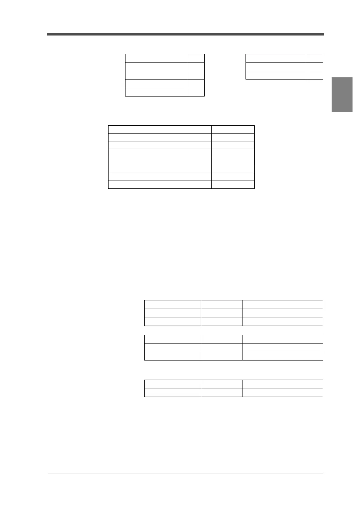
[Request]
Function 02
[Response]
Function 02
Start address (HI) 00 Data bytes 01
Start address (LO) 00 Hold to OK output 20
Number of inputs (HI) 00
Number of inputs (LO) 08
Hold OFF (0)
Stable OFF (0)
Near zero output OFF (0)
Overload (LOAD, OFL, Alarm) OFF (0)
Zero tracking OFF (0)
HI output ON (1)
LO output OFF (0)
OK output OFF (0)
[Request]
Function 1 byte 0x03
Start address 2 byte 0x0000 to 0xFFFF
Number of registers 2 byte 1 to 125 (0x7D)
[Response]
Function 1 byte 0x03
Data bytes 1 byte 2×N *
Register value N x 2 bytes
[Error response]
Error code 1 byte 0x83 (function +0x80)
Exception code 1 byte 01 or 02 or 03

 Loading...