21
2 Installation & Connection
21
Installation & Connection
Chapter
2
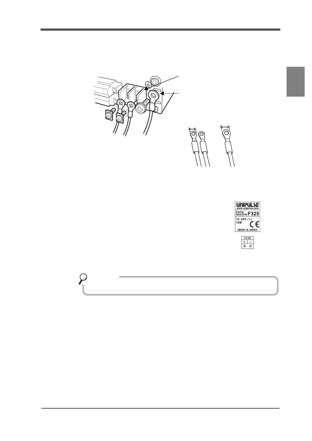
■DC spec. (specified at the time of order)
DC power supply may be used on the F325 if specified at the time of ordering.
DC power cord is connected.
Input voltage is DC12V to 24V between F325 terminals.
1. Ensure that the power is off.
2. Remove the terminal block cover.
3. Remove the power input terminal block screws (two
points) and protective grounding.
4. Fit crimping terminals into screw holes and secure
them with screws.
+:Red screw
-: Black screw
5. Attach the terminal block cover.
+-
Protective grounding (M4)
5.8mm or less
+
-
DC IN
Protective grounding
Power supply terminal block (M3)
10mm or less
The following print
on the sticker affixed to
the main unit.
DC power cord is not included as standard.
Key points