19
2 Installation & Connection
19
Installation & Connection
Chapter
2
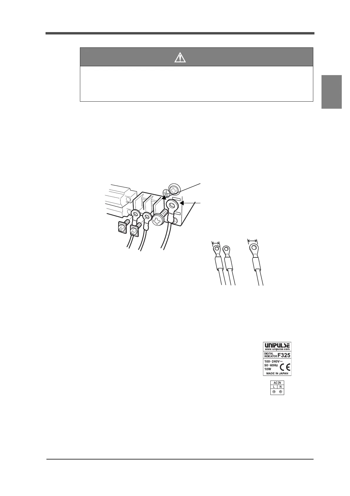
2-9. Power input terminal connection
■AC spec.
AC input cord is connected. Input voltage is AC100 to 240V.
Frequency is 50/60Hz.
1. Ensure that the power is off.
2. Remove the terminal block cover.
3. Remove screws of the power input terminal block (two
points) and protective grounding.
4. Fit crimping terminals into screw holes and secure
them with screws.
L: Black
N: White
Protective grounding: Green
5. Attach the terminal block cover.
Caution
● An external element must be an element in which Ic=20mA or more can be applied.
● External element leak must be 400μA or below.
● ON: DC9V or above, OFF: DC3V or below
LN
Protective grounding (M4)
5.8mm or less
Black White Green
(The indicated colors correspond to the AC cable included.)
L
N
AC IN
Protective grounding
Power supply terminal block (M3)
10mm or less
The following print
on the sticker affixed to
the main unit.