113
13 Options
113
Options
Chapter
13
BCD data hold - Level input
Update of BCD data output signals is stopped. (Indicated values are not held.)
STROBE output is also turned OFF.
Hold is performed at A14 pin.
Logic selection - Level input -
Logic of output signals is selected. Selection is performed at B14 pin.
■Source type (BSC option)
Output
Output signal: Indicated value data (five-digit), 80000/near zero*, minus, OVER, stable,
STROBE
* Switch with setting value of BCD B9 output selection.
Output logic: Positive/negative logic selection
Output format: Source type
Output transistor shall be ON when the signal is ON.
When connecting input units such as PLC, connect a minus common type.
Rated voltage: 30V
Rated current: 20mA
Insulation method: Photo-coupler insulation
Input
Input signal: BCD data hold, logic selection
Input format: Minus common input
Use a PNP output type (source type) when connecting transistors.
ON voltage: 9V or higher
OFF voltage: 3V or less
At 24V load: Approx. 5mA
Insulation method: Photo-coupler insulation
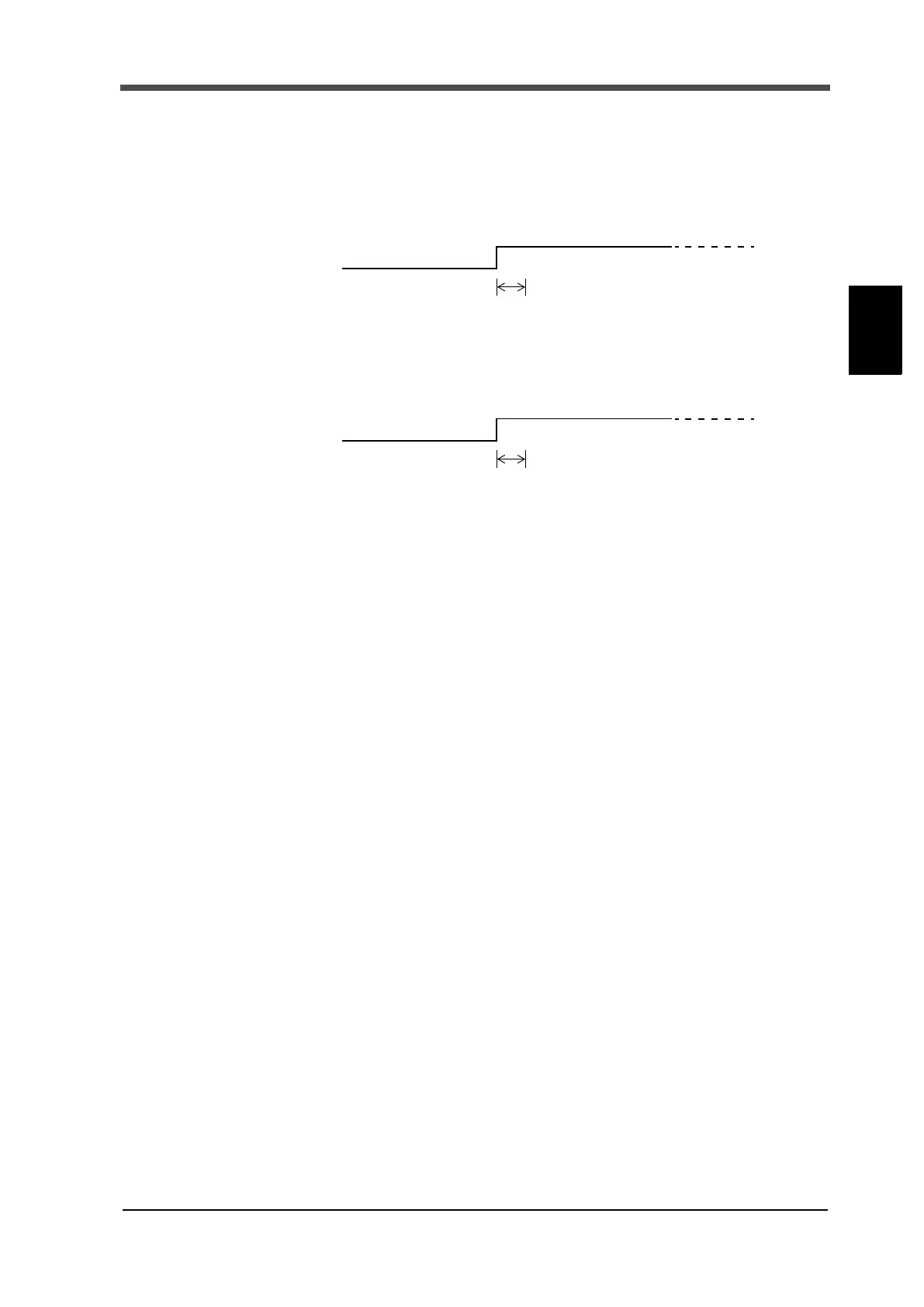
ON
OFF
Undefined section (within 5mSec)
Hold release when OFF and hold when ON.
Hold release
Hold
ON
OFF
Undefined section (within 5mSec)
Negative logic when OFF, and positive logic when ON.
Negative logic
Positive logic