74
10 Analog Monitor Output (VOL OUT)
74
Analog Monitor Output (VOL OUT)
Chapter
10
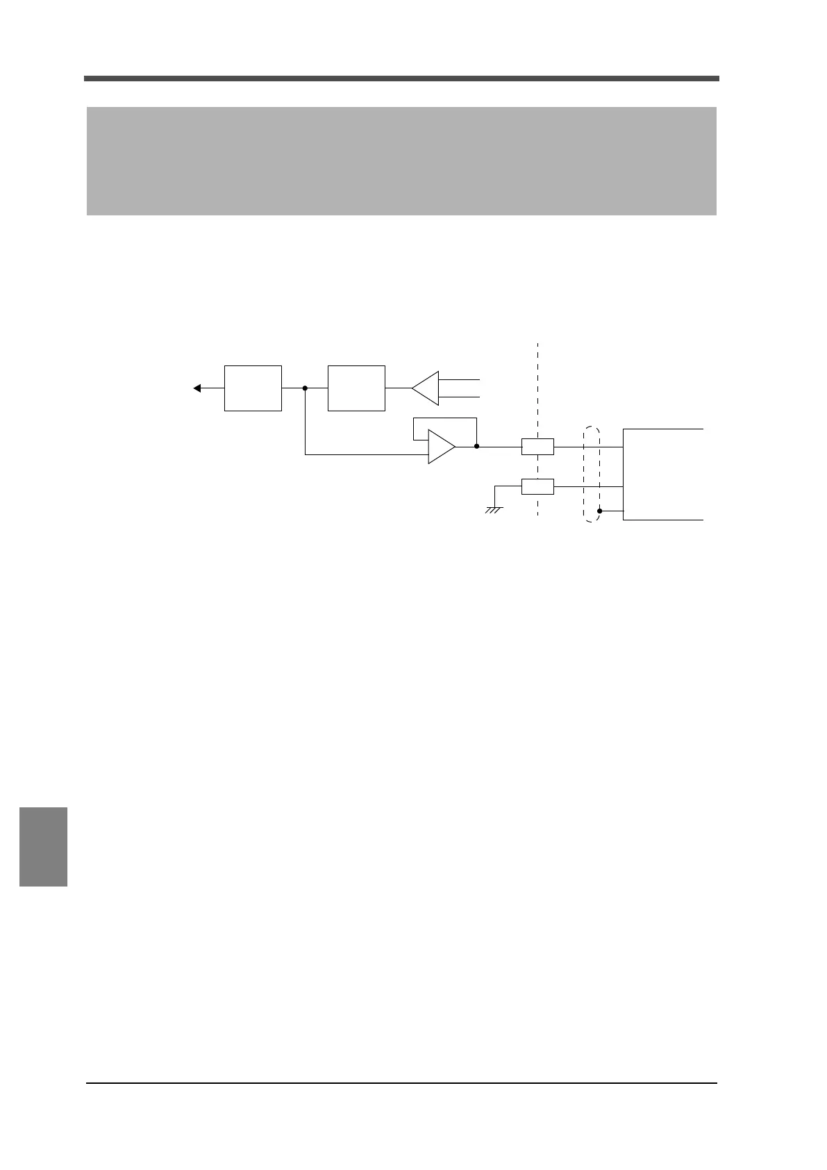
This interface is used for retrieving an analog voltage proportional to a sensor input signal. This
interface connects a recorder and so on and is useful for measuring and recording waveforms. An
output level is approx. 2V per sensor input 1mV/V.
Example of connecting output equivalent circuit and external device
The output voltage is not an indicated value since it is retrieved from the front stage where sensor
input signals are A/D converted.
Therefore, this output voltage is not linked with indicated values digitally processed such as digital
zero and moving average filter. An output linked with indicated values requires an optional D/A
converter.
10Analog Monitor Output
(VOL OUT)
+
-
External
B6
B7
-
+
Inside F325
+
-
Analog
A/D
+SIG
-SIG
F.G
+
G
filter
Analog
peak
hold
device