12
2 Installation & Connection
12
Installation & Connection
Chapter
2
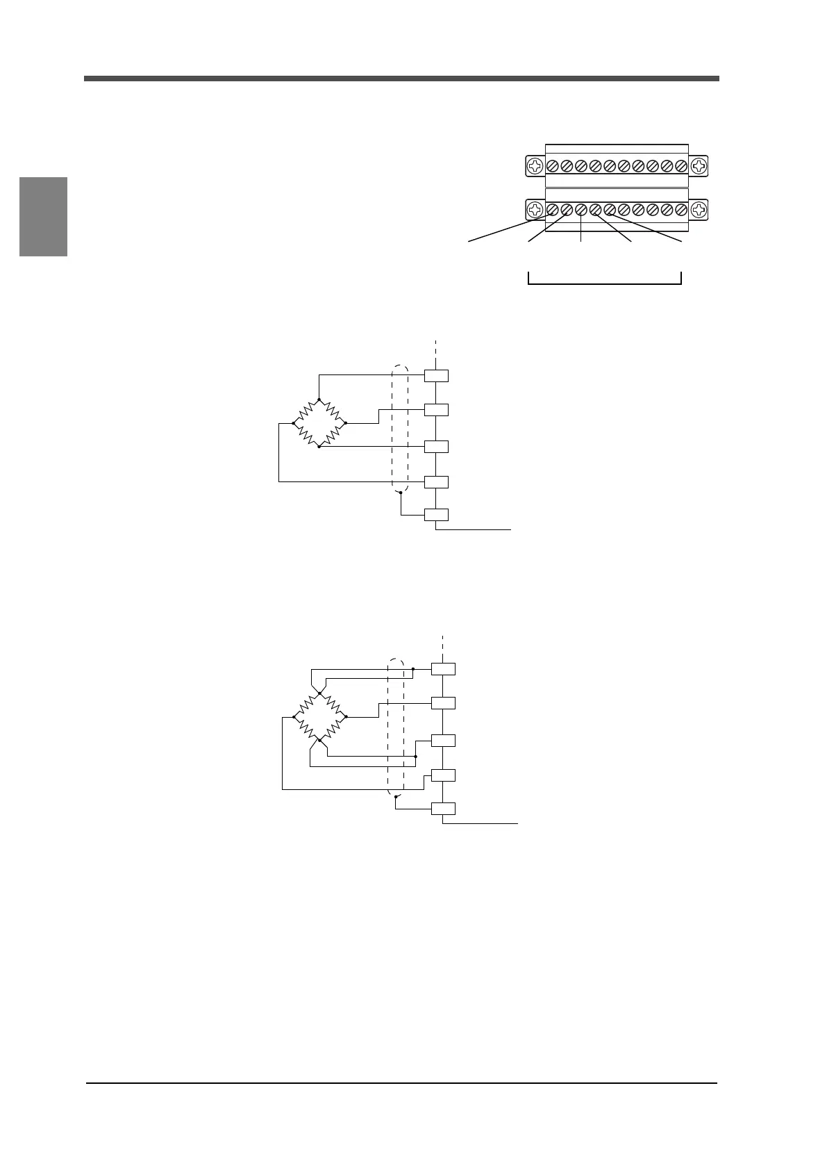
2-3. Connection of strain gauge type sensors
Strain gauge type sensors are connected.
Excitation voltage can be selected from
2.5 or 10V (factory setting = 2.5V).
Output current is 30mA maximum.
Refer to P.31 “4-5.Excitation voltage”
for excitation voltage settings.
◇Four-wire sensor
◇Six-wire sensor
Short-circuit +EXC and +S, and -EXC and -S, respectively, if connecting six-wire strain gauge type
sensors.
◇Cable colors of sensors
Cable colors of sensors may differ from one manufacturer to another (it may even differ from one
model to another for some products). Refer to the sensor manual (or data sheet) and check signal
names and colors in order to connect the cables correctly.
B2 B3 B4 B5
Inputs of strain gauge type sensors
+EXC -SIG -EXC +SIG
B1
SHIELD
+EXC
-EXC
+SIG
-SIG
SHIELD
+IN
-OUT
-IN
+OUT
F325
B2
B3
B4
B5
B1
+EXC
-EXC
+SIG
-SIG
SHIELD
+IN
-OUT
-IN
+OUT
F325
+S
-S
B2
B3
B4
B5
B1