93
12 Interface
93
Interface
Chapter
12
Note that the relative address is 0x00 when writing in hold ON.
The example shows how ON (1) and OFF (0) of the F325 is rewritten.
Unused bits are filled with 0.
* Consider the read/write of coil to be completed by the normal responses.
* Do not execute commands in the address combinations below.
When executed, commands will be carried out one by one, but may not operate properly.
- Addresses 00001 and 00002
- Addresses 00003 and 00004
- Addresses 00005 and 00006
- Addresses 00007 and 00008
- Addresses 00009 and 00010
- Addresses 00011 to 00013
16 (0x10) Write Multiple Registers
For slave holding registers, data of the specified numbers is changed from a specified address.
When broadcast (0) is specified, holding registers of all slave devices with the same address are
rewritten.
The register address, number of registers and data for request are specified.
Slave devices transmit data by converting the contents of each register to 2 bytes.
*: N = Number of registers
Coil 00008 00007 00006 00005 Digital
zero
reset
Digital
zero
Hold
OFF
Hold
ON
Bit 00000101
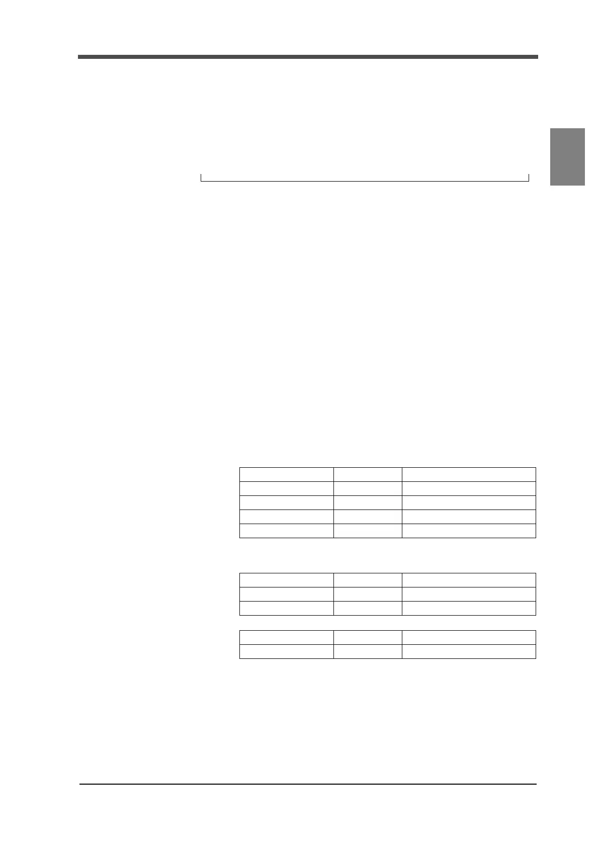
[Request]
Function 1 byte 0x10
Start address 2 byte 0x0000 to 0xFFFF
Number of registers 2 byte 0x0001 to 0x0078 (120)
Number of bytes 1 byte 2×N *
Changed data N x 2 bytes
[Response]
Function 1 byte 0x10
Start address 2 byte 0x0000 to 0xFFFF
Number of registers 2 byte 0x0001 to 0x007B (123)
[Error response]
Error code 1 byte 0x90 (function +0x80)
Exception code 1 byte 01 or 02 or 03

 Loading...