Parameter Value Associated apparatus entity
parameters
I
i
100 mA I
o
≤ I
i
P
i
700 mW P
o
≤ P
i
C
i
12.1 nF C
o
≥ C
i
+ C
cable
L
i
16 µH L
o
≥ L
i
+ L
cable
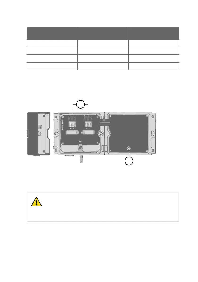
Using analog output test points
There are test points for measuring the voltages and currents of the analog outputs, located
above each screw terminal block as shown in Figure 10 (page 37). Accessing the test points
on the component board requires opening the transmitter enclosure.
mA
V
mA
V
CH1
CH2
A
Service Port
Use only in safe area
!
Do not remove this cover
1
2
Test Points
Figure 10 Location of test points and service port
1
Multimeter test points for analog output channels 1 and 2
2 Service port for PC connection
The transmitter body enclosure must not be opened in an explosion
hazardous area, unless a safe work permit has been issued in accordance with
the standard IEC 60079-14. Either remove the transmitter from the hazardous
area before opening the enclosure, or ensure that an IEC 60079-14 compliant
safe work procedure has been implemented in the hazardous area.
CAUTION!
Use an intrinsically safe multimeter that won't cause the intrinsically safe input parameters
listed in Table 16 (page 36) to be exceeded when it is connected in series (current
measurement) or parallel (voltage measurement) to the associated apparatus.
Chapter 3 – HMT370EX regional safety certification information
37