Connect only de-energized wires. Never switch on the power supply
input before completing the wiring and closing the transmitter body.
CAUTION!
Intrinsic safety
The overvoltage category of HMT370EX transmitters is I (non-mains equipment), and ambient
pollution degree is 4, as specified in IEC 60664-1. For intrinsically safe input parameters, see
Table 25 (page 54).
Table 25 Intrinsically safe input parameters
Parameter Value Associated apparatus entity
parameters
U
i
28 VDC U
o
≤ U
i
I
i
100 mA I
o
≤ I
i
P
i
700 mW P
o
≤ P
i
C
i
12.1 nF C
o
≥ C
i
+ C
cable
L
i
16 µH L
o
≥ L
i
+ L
cable
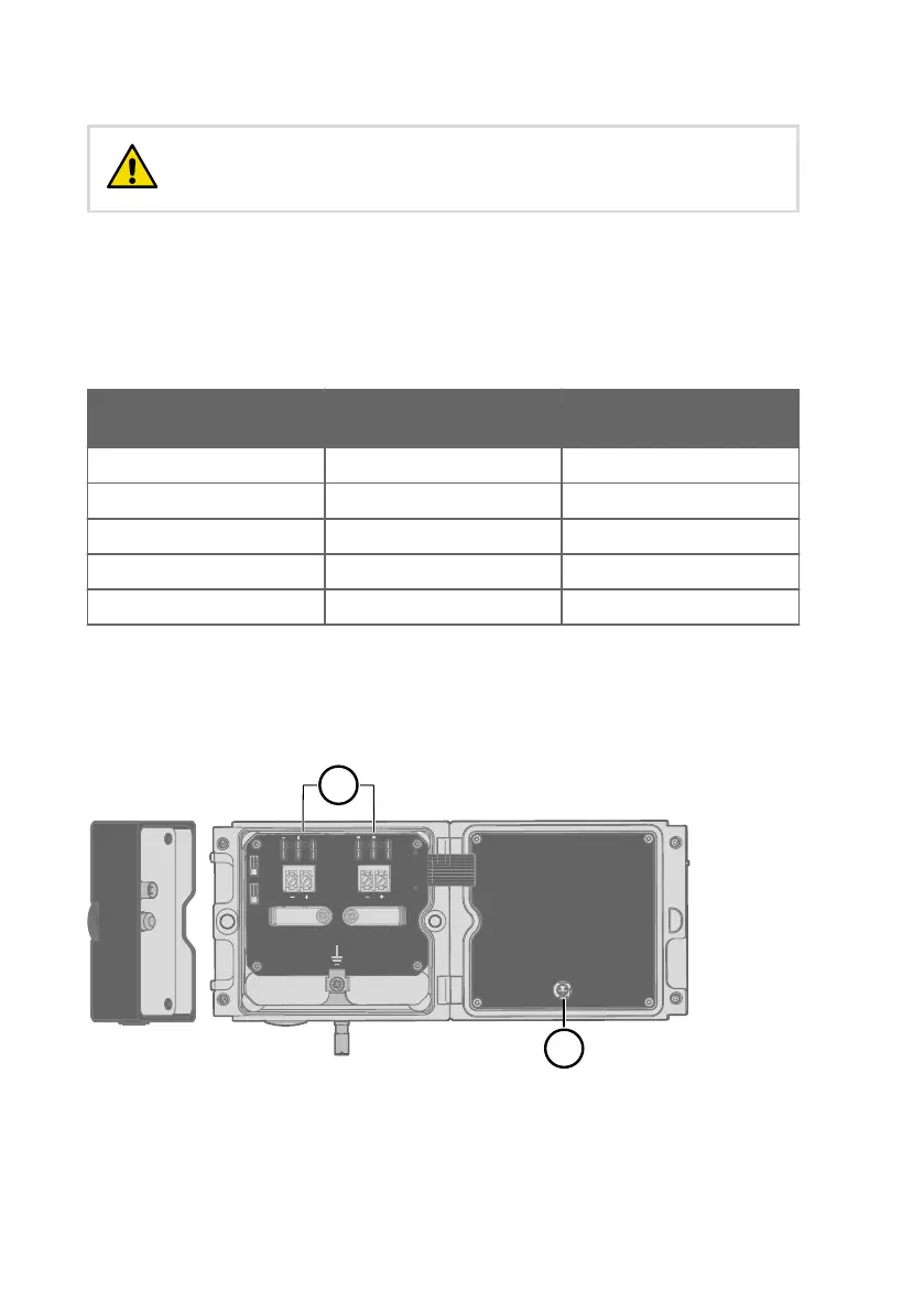
Using analog output test points
There are test points for measuring the voltages and currents of the analog outputs, located
above each screw terminal block as shown in Figure 17 (page 54). Accessing the test points
on the component board requires opening the transmitter enclosure.
mA
V
mA
V
CH1
CH2
A
Service Port
Use only in safe area
!
Do not remove this cover
1
2
Test Points
Figure 17 Location of test points and service port
1
Multimeter test points for analog output channels 1 and 2
2 Service port for PC connection
HMT370EX User Guide M212305EN-B
54