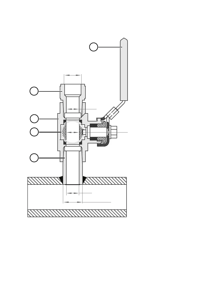
4.8.2 Attaching ball valve kit to process
G1/2
ISO 228/1
Ø21.5 (drilling)
Ø14
Ø14
Ø14
2
3
4
5
1
1 Ball valve handle: must point to the same direction as the ball valve body when installing.
2 Extension nipple, threads G1/2 ISO228/1 and R1/2 ISO7/1.
3 Ball valve body. When tightening the assembly, turn only from the ball valve body.
4 Ball of the ball valve.
5 Welding joint, threads R1/2 ISO7/1.
Chapter 4 – Probe options
75