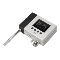
When HMT370EX is powered, the transmitter enclosure must not
be opened in a hazardous area. The probe can be detached and changed
when HMT370EX is powered. Any other live maintenance, including changing
the probe head filter, is not allowed.
WARNING!
• Screws for mounting the transmitter:
• Installation directly through the transmitter body: 2 pcs Ø 5.5 mm screws
• Installation with optional mounting plate: 4 pcs Ø 5.5 mm screws and 2 pcs
M6 Allen screws
• Crosshead screwdriver for transmitter cover captive screws and wiring screw
terminals
• Flathead screwdriver for the grounding terminal
• Cable glands, conduits, and plugs as required in your application, and suitable
tools for attaching and tightening them
• Wire-cutting pliers
Optional:
• Crimping tool and wire ferrules
• Allen key (5 mm) for probe body locking wheel
• Ex-compliant multimeter for testing analog outputs
5.1.1 Installation preparations
Before starting the installation, check the following:
• Make sure that your installation site suits the Ex classification of the transmitter (for
classification information relevant to your region, see Regional safety certification
overview (page 19)).
• Review the hazardous area information relevant to your region (see Regional safety
certification overview (page 19)) for further information on Ex safety requirements related
to HMT370EX and specific conditions of use.
• When selecting the cable glands and plugs for your application, review the information in
Cable gland and conduit options (page 17).
• Review the wiring diagrams included in this document for information on wiring using
either a galvanic isolator or a Zener barrier.
• Wiring with galvanic isolators (page 88)
• Wiring with Zener barriers (page 89)
Protected installation using galvanic isolators or Zener barriers is
mandatory in a hazardous environment.
WARNING!
When planning the wiring of your application, note that Channel 1
(CH1) must always be wired. The transmitter receives power through the
Channel 1 screw terminals, and does not power on if only Channel 2 (CH2) is
wired.
CAUTION!
HMT370EX User Guide M212305EN-B
82

 Loading...