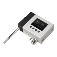
2. Mount the transmitter body on the installation surface either directly through the
transmitter body, or using the optional HMT360 retrofit mounting plate:
a. Installation without mounting plate: attach the transmitter body directly to the
installation surface with 2 Ø 5.5 mm screws as shown in Figure 35 (page 84). The left-
hand screw hole has extra vertical space for adjusting the position of the transmitter
after you have attached the right-hand screw.
b. Installation with mounting plate: attach the mounting plate to the installation surface
with 4 Ø 5.5 mm screws, and then attach the transmitter to the mounting plate with 2
M6 Allen screws.
5.3 Attaching cable glands and conduit fittings
The HMT370EX transmitter body has 2 lead-throughs (M20x1.5) for wiring. The combination of
cable glands, conduit fittings, and plugs used in the lead-throughs is application-specific, and
must be determined by the customer. For information on lead-through accessories available
from Vaisala and lead-through accessory requirements, see Cable gland and conduit options
(page 17).
If you use lead-through accessories not ordered from Vaisala, note
the following requirements:
• The cable glands and cables used for wiring the device must not impair the Ex
protection.
• Unused lead-throughs must be sealed using Ex compliant plugs.
• The glands and plugs must be water and dust tight.
CAUTION!
Chapter 5 – Installation
85

 Loading...